
Ultra low-power data retention latch

a low-power, data-retaining circuit technology, applied in the direction of pulse generators, pulse techniques, electrical apparatus, etc., can solve the problems of inability to activate the main latch, undesired slowing data throughput, and more time for the main latch to correctly resolv

Active Publication Date: 2005-11-15
TEXAS INSTR INC
View PDF2 Cites 16 Cited by
  • Summary
  • Abstract
  • Description
  • Claims
  • Application Information

AI Technical Summary

Problems solved by technology

However, in some known arrangements, there is a need to explicitly disable the main latch while awaiting or during stable power restoration.
Also, some known latch arrangements require additional isolation or buffer circuitry, or have a circuit topology, that effectively add to the time required to pass data through the latch, undesirably slowing data throughput.
For example, in certain conventional retention latches, the back-up latch's lines are connected the data output nodes of the main latch, adding loading to the main data path; undesirably, more time is needed for the main latch to correctly resolve before the main data path can safely be enabled.
Also, certain known arrangements require power to the main latch to be kept off until data is restored to the normal output path, slowing the circuit's return to normal operation.
Furthermore, some conventional latch arrangements simply consume undesirably large amounts of power.

Method used


Image

  • Ultra low-power data retention latch
  • Ultra low-power data retention latch
  • Ultra low-power data retention latch

Examples


Embodiment Construction

[0011]In describing embodiments illustrated in the drawings, specific terminology is employed for the sake of clarity. However, the invention is not intended to be limited to the specific terminology so selected, and it is to be understood that each specific element includes all technical equivalents that operate in a similar manner to accomplish a similar purpose. Various terms that are used in this specification are to be given their broadest reasonable interpretation when used to interpret the claims.

[0012]Moreover, features and procedures whose implementations are well known to those skilled in the art are omitted for brevity. For example, design, selection, and implementation of basic electronic circuit elements such as signal level shifters, buffers, logic elements, current and voltage sources, diodes, bipolar transistors, metal oxide semiconductor field effect transistors (MOSFETs), transmission gates, delay elements, and the like, lie within the ability of those skilled in t...


PUM


Abstract

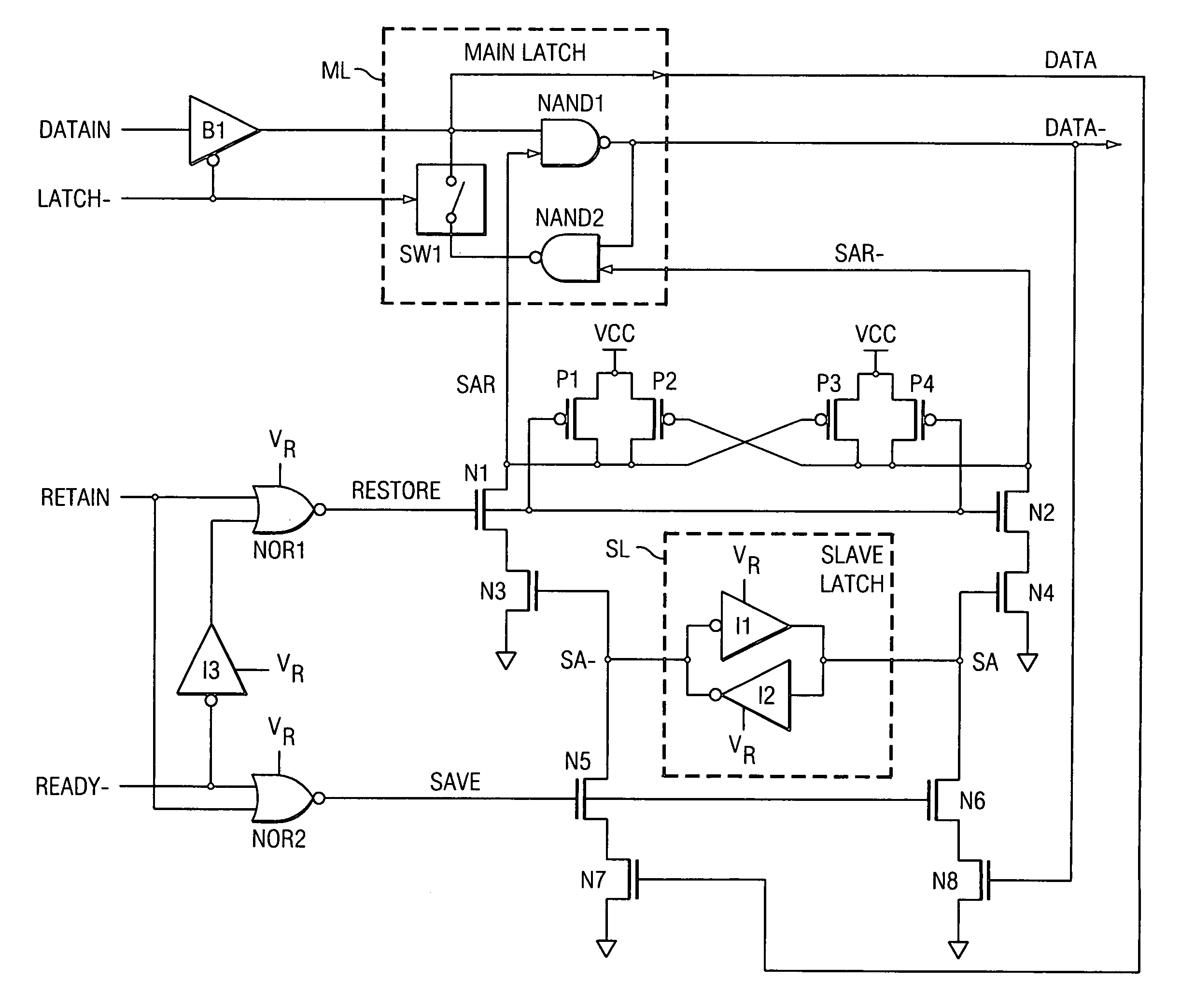
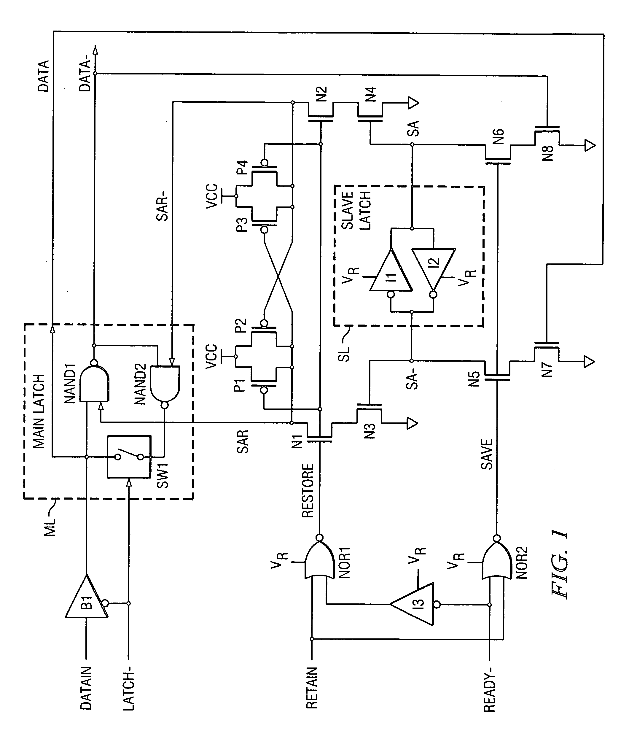
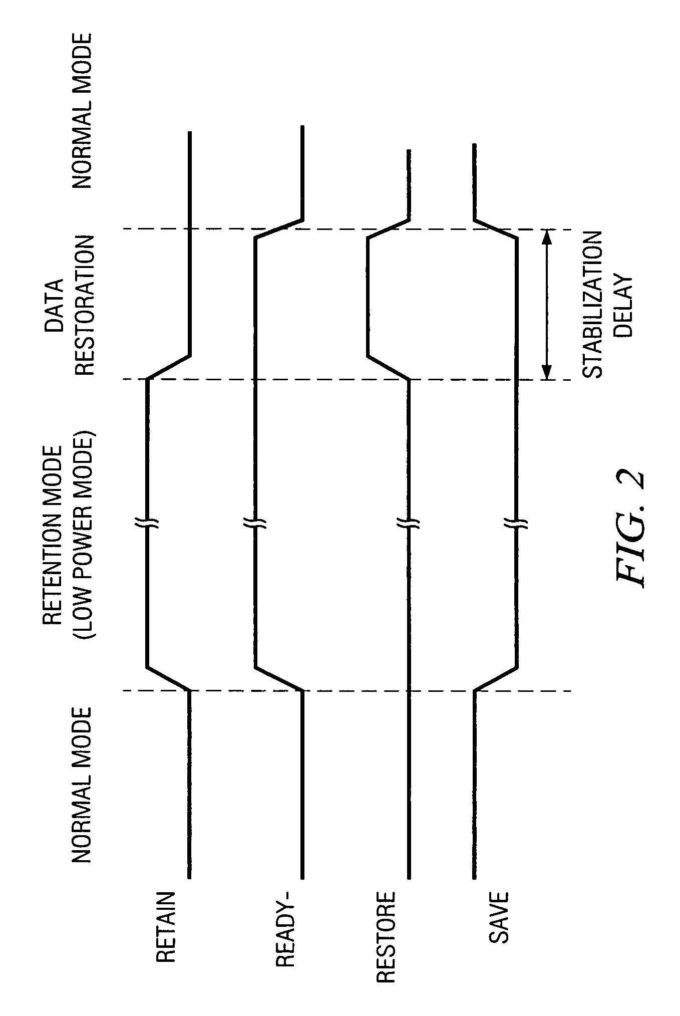
An embodiment of a ultra low-power data retention latch circuit involves a slave latch SL that concurrently latches the same data that is loaded into a main circuit (such as a main latch ML) during normal operation. When the circuit enters a low power (data retention) mode, power (VCC) to the main latch ML is removed and the slave latch SL retains the most recent data (retained data SA, SA-). When power is being restored to the main latch ML, the slave latch's retained data SA, SA- is quickly restored to the main latch ML through what constitute Set and Reset inputs SAR, SAR- of the ML. This arrangement ensures that data restoration is much quicker than conventional arrangements that require the output data path DATA- to be stabilized before power is re-applied to the main latch. Further, there is no need to wait for power to the ML to be stable before restoring data from the SL to the ML, providing an increase in data restoration speed over conventional data retention latches. Using retained data SA, SA- (as mirrored in SAR, SAR-) to control the Set and Reset inputs prevents data contention in the main latch ML. Moreover, compared to known arrangements, the arrangement provides minimal loading on the DATA, DATA- output paths (driving only N7, N8), thus not compromising speed on the data path (DATAIN . . . DATA / DATA-) through the main latch during normal operation.

Description

BACKGROUND OF THE INVENTION[0001]1. Field of the Invention[0002]The invention generally relates to data retention circuits that retain data during a “low power mode” in which power is removed from certain main circuitry. More particularly, the invention relates to ultra low-power data retention circuits in which it is desired to quickly save data from a main latch to a slave latch, and to quickly replenish the main data latch with retained data, all while minimally loading main data latch data output lines during normal operation.[0003]2. Related Art[0004]In low-power chips, much of the circuitry is shut down when not in use (in a “low power mode”) so as to conserve power. However, some parts of the circuit remain powered during low power mode, to retain data. This retained data is used again when the chip emerges from low power mode.[0005]Various back-up data latch arrangements are known in the art. However, in some known arrangements, there is a need to explicitly disable the main...

Claims


Application Information

Patent Timeline
Patent Type & Authority Patents(United States)
IPC IPC(8): H03K3/012H03K3/037H03K3/00H03K3/3562
CPCH03K3/012H03K3/0375
Inventor TRAN, TAM MINHJAMISON, GEORGE B.
Owner TEXAS INSTR INC
Learn More