Eureka AIR delivers breakthrough ideas for toughest innovation challenges, trusted by R&D personnel around the world.

Disc-media storage case and printed-media storage tray

a technology for disc media and storage cases, applied in the field of portable cases, can solve the problems of not providing for the inclusion of printed graphic labels with cd discs or manual handling of cd jewel cases, and the device does not address the problems of jewel cases, etc., and achieves the effect of not being able to see the booklet or any other labeling material on the disc from the side of the cas

Inactive Publication Date: 2005-11-15
DIGITAL DISC CORP
View PDF57 Cites 13 Cited by
  • Summary
  • Abstract
  • Description
  • Claims
  • Application Information

AI Technical Summary

Problems solved by technology

This device does not address the problems of a jewel case.
For example, it does not provide for the inclusion of any printed graphic label material with the CD discs or the manual handling of a CD jewel case.
However, it is not possible to see the booklet or any other labeling material for the disc from the sides of the case.
This allows for efficient display of the titles and artists on the retail shelf space.” However, this structure does not allow for the standard spine graphics label used with standard CD cases to be used and seen from the spines or short-ends of the case.
A cam arrangement is provided for resiliently deflecting the arms outwardly to a deflected position to disengage the capture points from the side edges of the disc thereby releasing the disc from the holder.” Again, this structure does not allow for the standard spine graphics label used with standard CD cases to be used and seen from the spines or short-ends of the case.
Again, this arrangement does not allow for the standard spine graphics label used with standard CD cases to be used and seen from the spines or short-ends of the case.
Furthermore, this design is complicated and expensive to manufacture.

Method used


Image

  • Disc-media storage case and printed-media storage tray
  • Disc-media storage case and printed-media storage tray
  • Disc-media storage case and printed-media storage tray

Examples


Embodiment Construction

Non-Limiting Terms And Specific Examples

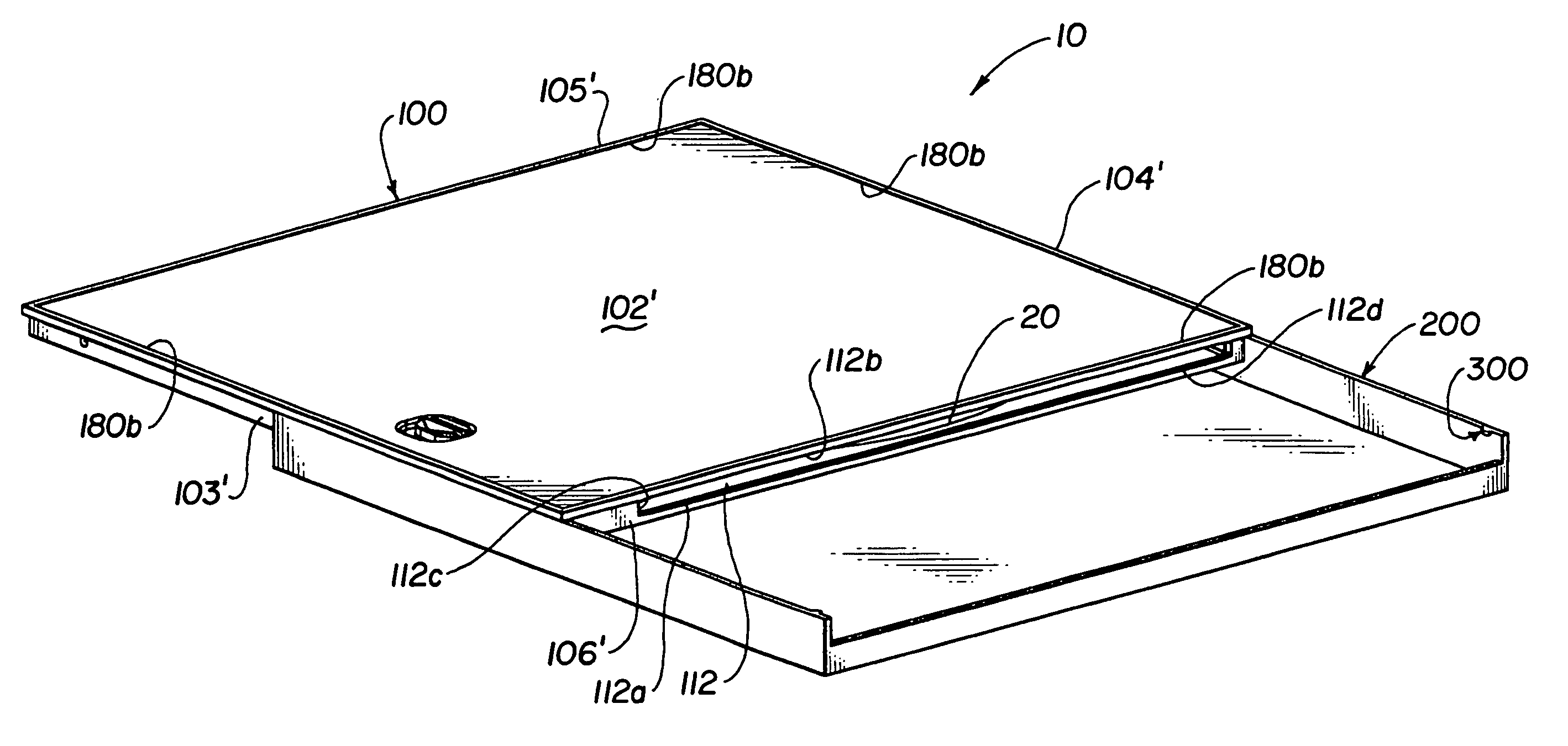
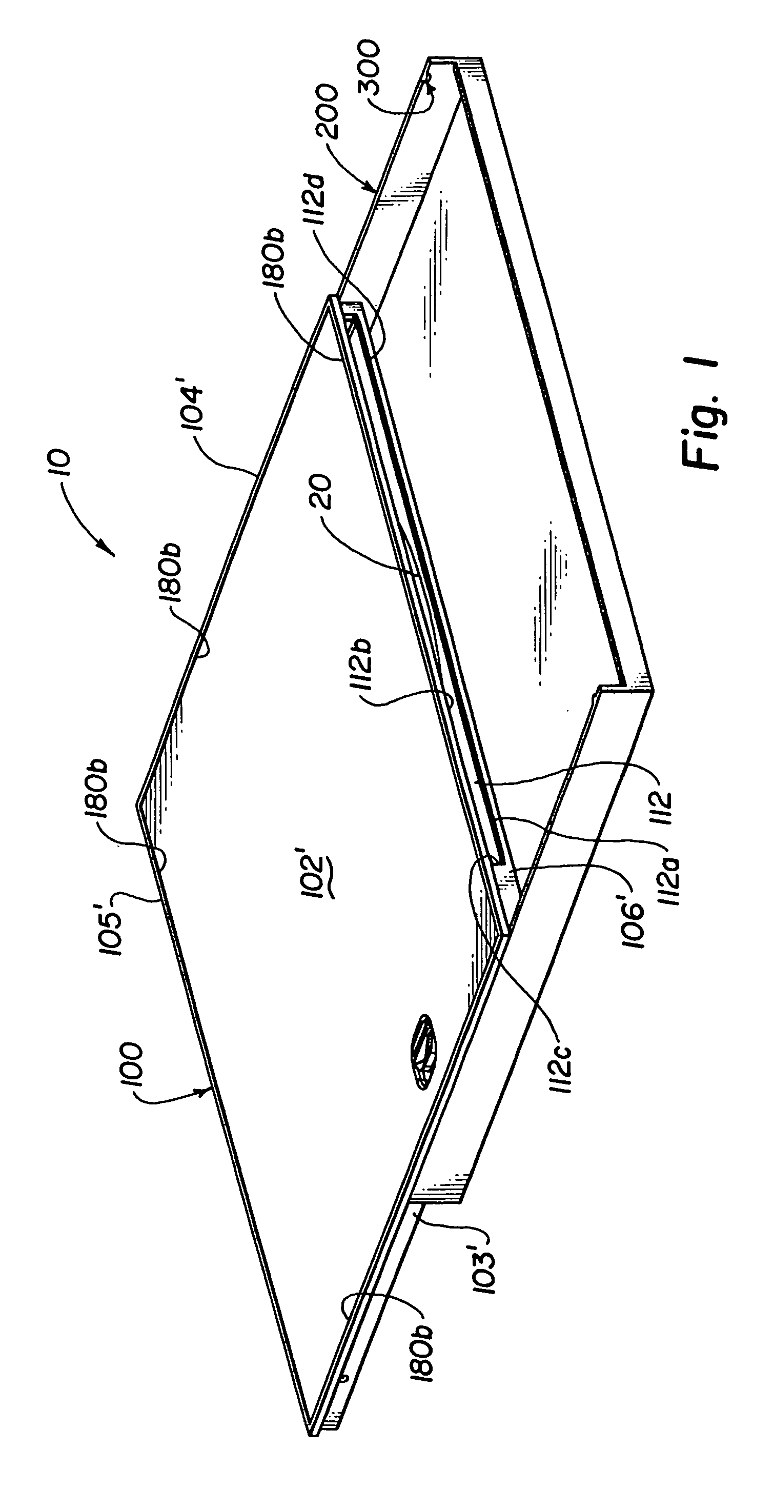
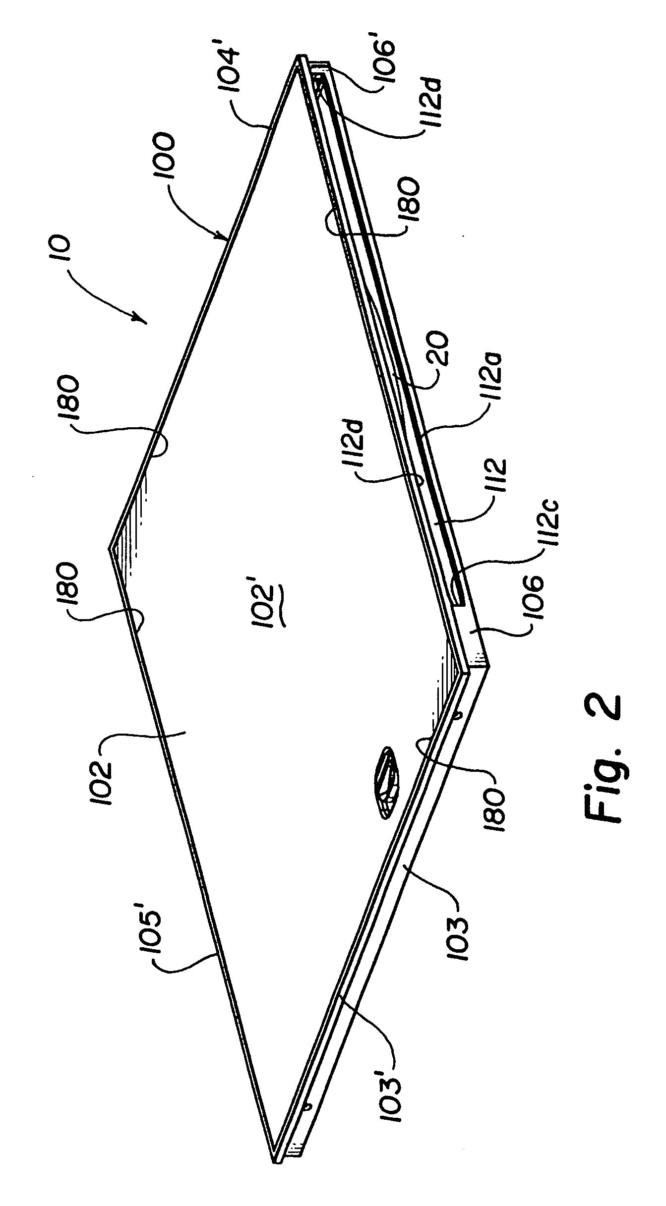
[0061]It is to be understood that, unless specially noted, that relational terms such as “base”, “bottom”, “lower”, “lid”, “top”, “upper”, “side”, “front”, “back”, “left”, “right”, etc. are arbitrarily assigned for convenient reference to the orientation and perspective of the figures of the drawing. Furthermore, it is to be understood that relative terms such as “length”, “width”, “height”, “thickness”, etc. are also arbitrarily assigned for convenient reference to the orientation and perspective of the figures of the drawing. For the sake of consistency of usage, once a term is first arbitrarily assigned for reference to a structure in a particular figure, the term will then be used consistently to refer to like parts throughout the other figures of the drawing, even if the orientation of a structure shown in another figure is different for the purpose of showing another feature of the preferred embodiment(s) of the invention. For example, i...


PUM

PropertyMeasurementUnit
Shapeaaaaaaaaaa
Heightaaaaaaaaaa

Abstract

A storage device for disc media is provided. The storage device includes at least a case for storing the disc media. The case generally includes a plurality of case walls defining a box-like shape, a cavity defined inside the case walls that is sufficient to accommodate the disc media, and an opening defined in a side of the case (which is arbitrarily referred to as the front side of the case), the opening being at least sufficient for inserting the disc media into the cavity. According to a first aspect of the invention, the storage device includes a tray for optionally storing printed media associated with the case and a structure for retaining the tray on the case. According to a second aspect of the invention, the storage device includes a structure for selectively controlling the release of the disc media from the case. These two aspects of the invention can be practiced independently, but most preferably and advantageously are practiced together.

Description

BACKGROUND OF THE INVENTION[0001]This invention relates to a portable case for a disc media where the disc media can be inserted and removed edgewise through a side of the case. More particularly, according to one aspect, this invention also relates to a storage device that includes storage space for both a disc media and for a printed media, such as a graphics label and / or a booklet. More particularly still, this aspect of the invention relates to a storage device for both a disc media and printed media, where at least a portion of the printed media can be seen from a side or “spine” of the storage device. According to another aspect, this invention relates to case for disc media that includes an improved structure for selectively controlling the release of the disc media from the case. Furthermore, this invention also relates to designs for a storage device that improves and simplifies the manufacturing of such a storage device for a disc media, and, optionally, printed media. Thi...

Claims


Application Information

Patent Timeline
IPC IPC(8): B65D85/30G11B33/04
CPCG11B33/0422
Inventor HARRIS, CHARLES D.
Owner DIGITAL DISC CORP
Why Eureka
Eureka Blog
Learn More