
Method for receiving a radio frequency (RF) signal and RF receiver

a radio frequency and receiver technology, applied in the field of method and arrangement for receiving a radio frequency (rf) signal, can solve the problems of short period between two consecutive bursts, short available time of operation between charging the batteries, and poor reception effect, so as to reduce the power consumption of the receiver and achieve stable receiving conditions

Inactive Publication Date: 2005-11-08
NOKIA TECHNOLOGLES OY
View PDF22 Cites 15 Cited by
  • Summary
  • Abstract
  • Description
  • Claims
  • Application Information

AI Technical Summary

Benefits of technology

[0006]It is an objective of this invention to provide a receiving method and a receiver that offers solutions to the prior art problems. Especially, it is an object of this invention to provide a solution for reducing a power consumption of the receiver, and still to maintain stable receiving conditions.
[0009]The present invention enables fast tuner lock-in time and still offers a considerable saving in total power consumption of the receiver.

Problems solved by technology

However, the mobile DVB receivers should be small-sized and lightweight with small-sized batteries.
Also, the available time of operation between charging the batteries should be long.
In achieving this, the power consumption of mobile DVB receivers may become a problem.
However, there are certain problems related with applying these solutions in a DVB receiver.
Firstly, the period between two consecutive bursts may be short and the tuner cannot be switched off, during the transmission break.
A further problem is related to a certain type of step-up converter.
The remaining supply voltage appears also in the tuner power supply line and consumes power.

Method used


Image

  • Method for receiving a radio frequency (RF) signal and RF receiver
  • Method for receiving a radio frequency (RF) signal and RF receiver
  • Method for receiving a radio frequency (RF) signal and RF receiver

Examples


Embodiment Construction

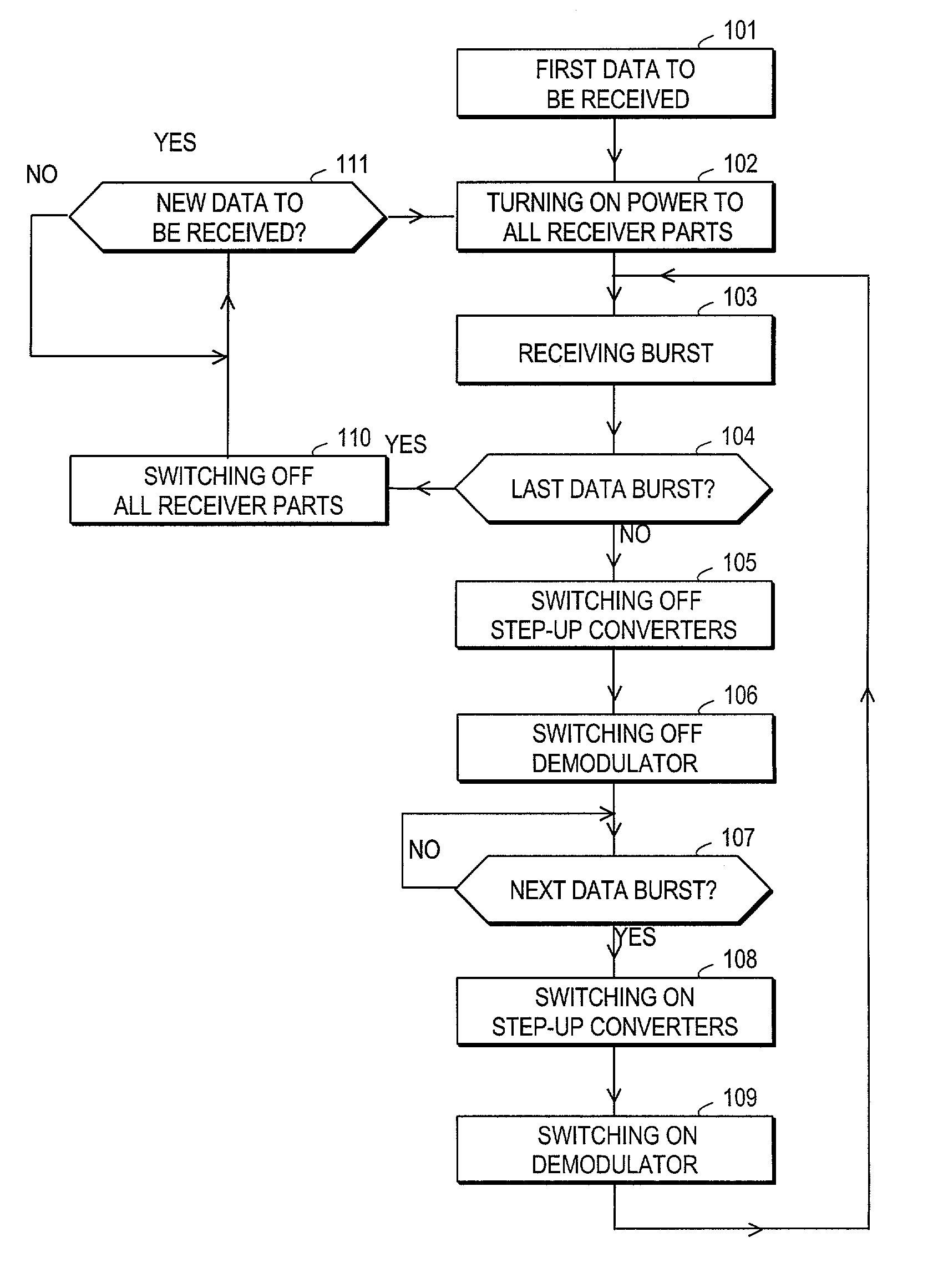
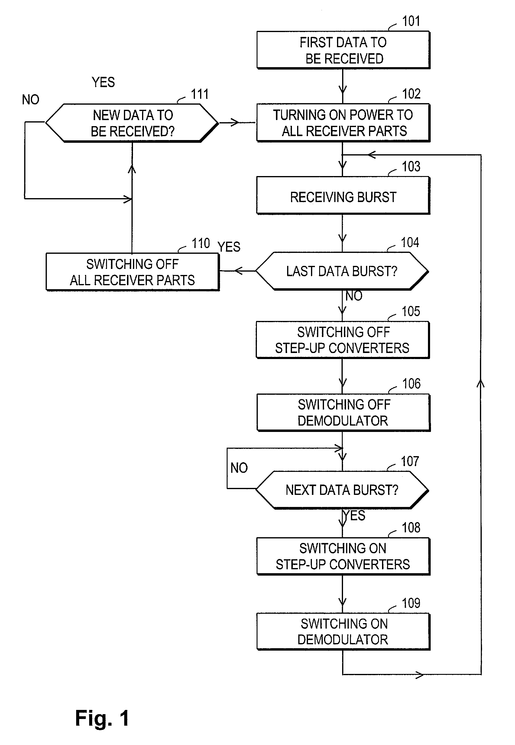
[0022]FIG. 1 illustrates a flow diagram of an example for a method according to the invention. When there is a data transmission to be received, 101, all receiver parts are turned on, step 102. A burst is then received on step 103, and after receiving the burst the step-up converters and the demodulator are turned off, 105, 106. However, at least some parts of the phase locked loop remain powered. The next burst is then awaited, 107. Since the RF signal processing of the receiver is in off state, the receiver cannot monitor the appearance of the next burst, so the receiver must have the information on the time instant when the next burst is to be received. This information may, for example, be based on predetermined time intervals between the bursts. When the next burst is to be received, 107, the step-up converters and the demodulator are switched on, 108, 109, and the next burst is received, 103.

[0023]When there is no further data to be received, 104, all RF signal processing part...


PUM


Abstract

The invention relates generally to a method and an arrangement for receiving a radio frequency (RF) signal and an RF receiver. Particularly the invention relates to controlling and reducing power consumption in a radio receiver. The invention can advantageously be applied in receiving arrangements of radio systems, wherein information is transferred in bursts, such as a receiver of Digital Video Broadcasting (DVB) system. According to the invention, during the time between two bursts the power supply is maintained in at least in some parts of the phase locked loop PLL (240), while one or several other parts (202, 204, 224, 225, 230, 262, 270) of the receiver are turned off for a certain time period between the two bursts. The present invention enables fast tuner lock-in time and still offers a considerable saving in total power consumption of the receiver.

Description

FIELD OF THE INVENTION[0001]The invention relates generally to a method and an arrangement for receiving a radio frequency (RF) signal, and an RF receiver. Particularly the invention relates to controlling and reducing power consumption in a radio receiver.BACKGROUND OF THE INVENTION[0002]In the following, DVB system and DVB receivers are described as examples, although the use of the invention is not restricted to the DVB system. Digital video broadcasting has been under development, and it is seen to gradually replace the analog broadcasting systems. This is because of its ability to offer new types of services and better quality of service. Digital Video Broadcasting has been under standardisation by European Broadcasting Union (EBU) and European Telecommunications Standards Institute (ETSI) that have created a DVB standard ETS 300 800. In the digital broadcasting system data is transferred in bursts within determined time slots. The modulation is e.g. Orthogonal Frequency Divisi...

Claims


Application Information

Patent Timeline
Patent Type & Authority Patents(United States)
IPC IPC(8): H04B1/16H04N5/44H04H1/00H04H20/42H04H40/18
CPCH04H20/42H04H40/18H04N5/4446H04W52/0283H04N5/4401Y02B60/50H04N21/426H04N21/4436Y02D30/70
Inventor TAHTINEN, IIKKA
Owner NOKIA TECHNOLOGLES OY
Learn More