
Arrangement of local area network

a technology of local area network and arrangement, applied in the field oflans, can solve the problems of twisted pair line, increase the cost of operators, and adsl techniqu

Inactive Publication Date: 2005-11-08
WI LAN INC
View PDF13 Cites 74 Cited by
  • Summary
  • Abstract
  • Description
  • Claims
  • Application Information

AI Technical Summary

Benefits of technology

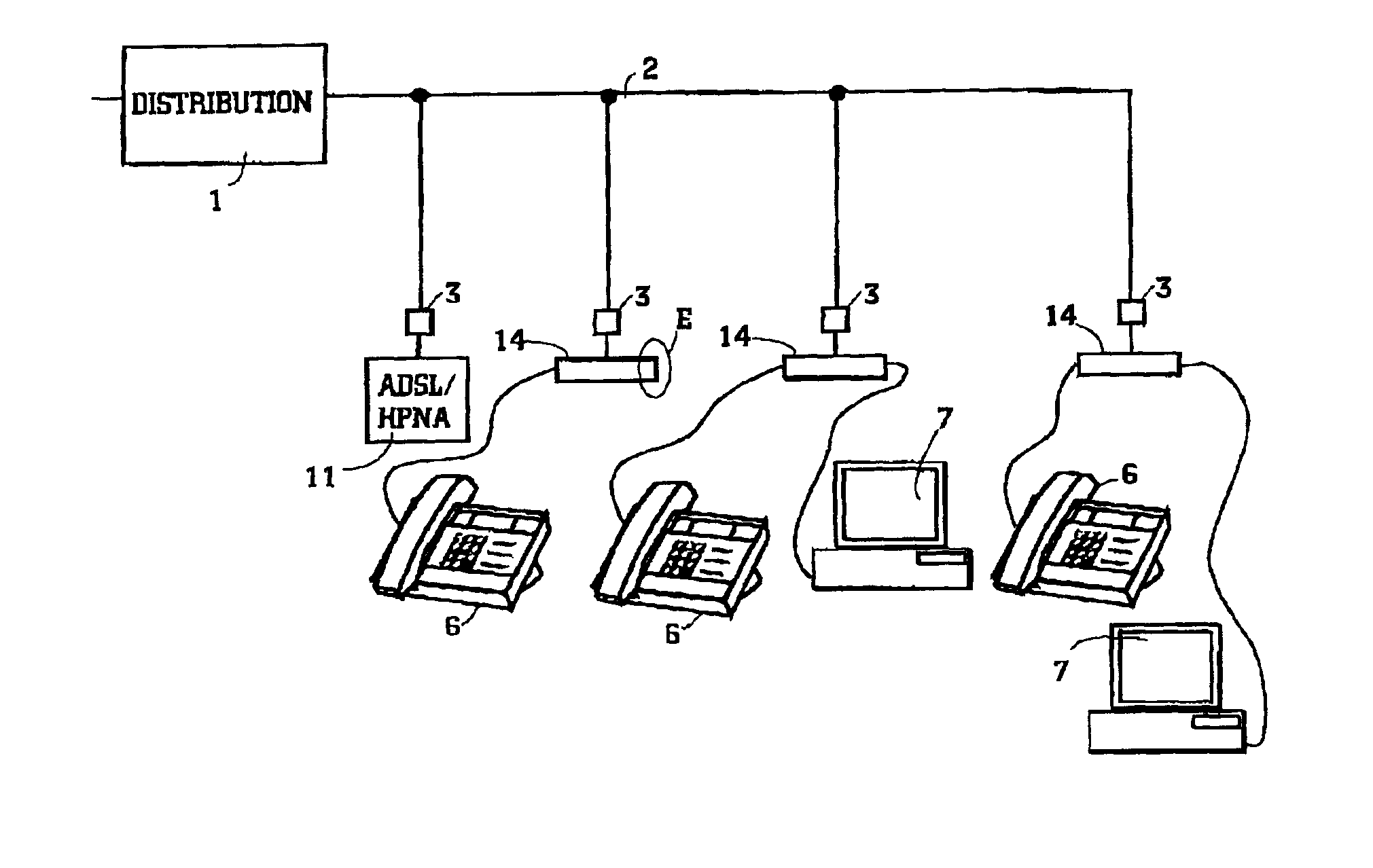
[0012]The idea of the invention is that a band division filter separates the POTS and HomePNA (HPNA) frequency ranges from the traffic carried by a distribution network in a way that the band division filter does not disturb the frequency range of ADSL. This is achieved by designing the HPNA filter part of the band division filter for maximizing the insertion loss in the frequency range of ADSL, i.e. maximizing impedance at the ADSL band. The band division filter can be installed to telephone sockets needed. So only one filter element type is needed to be delivered to a customer. The band division filter does not unnecessarily load the distribution network, if it is open, i.e. a HPNA device is not connected to it. The arrangement according to the invention also comprises an ADSL / HPNA gateway for making a conversion from ADSL signals to HPNA signals, and vice versa.

Problems solved by technology

There are some problems in the ADSL technique.
Another problem is that a twisted pair line has to transmit both the original POTS (Plain Old Telephone System) traffic and the ADSL traffic.
The installation of the splitter and the division of the network requires a visit from an installer, which increases the operator's costs and is annoying for the customer.
That is not possible when using wireless or power supply transmission, since in these cases the transmission media carries traffic of several customers.
It is possible to encrypt the traffic, but congestion may occur when several customers use the same transmission media.
However, there are some difficulties in realizing a HomePNA network, particularly when a customer is an ADSL subscriber.
This may work nice if a customer is a POTS subscriber (the gateway to the outside is a cable modem and the subscriber loop is a POTS line), but if the customer is an ADSL subscriber (the gateway to the outside is an ADSL modem and the subscriber loop is an ADSL line), the situation is much more complex.
An ADSL line is very sensitive to external loads—especially a nonlinear load is fatal.

Method used


Image

  • Arrangement of local area network
  • Arrangement of local area network
  • Arrangement of local area network

Examples


Embodiment Construction

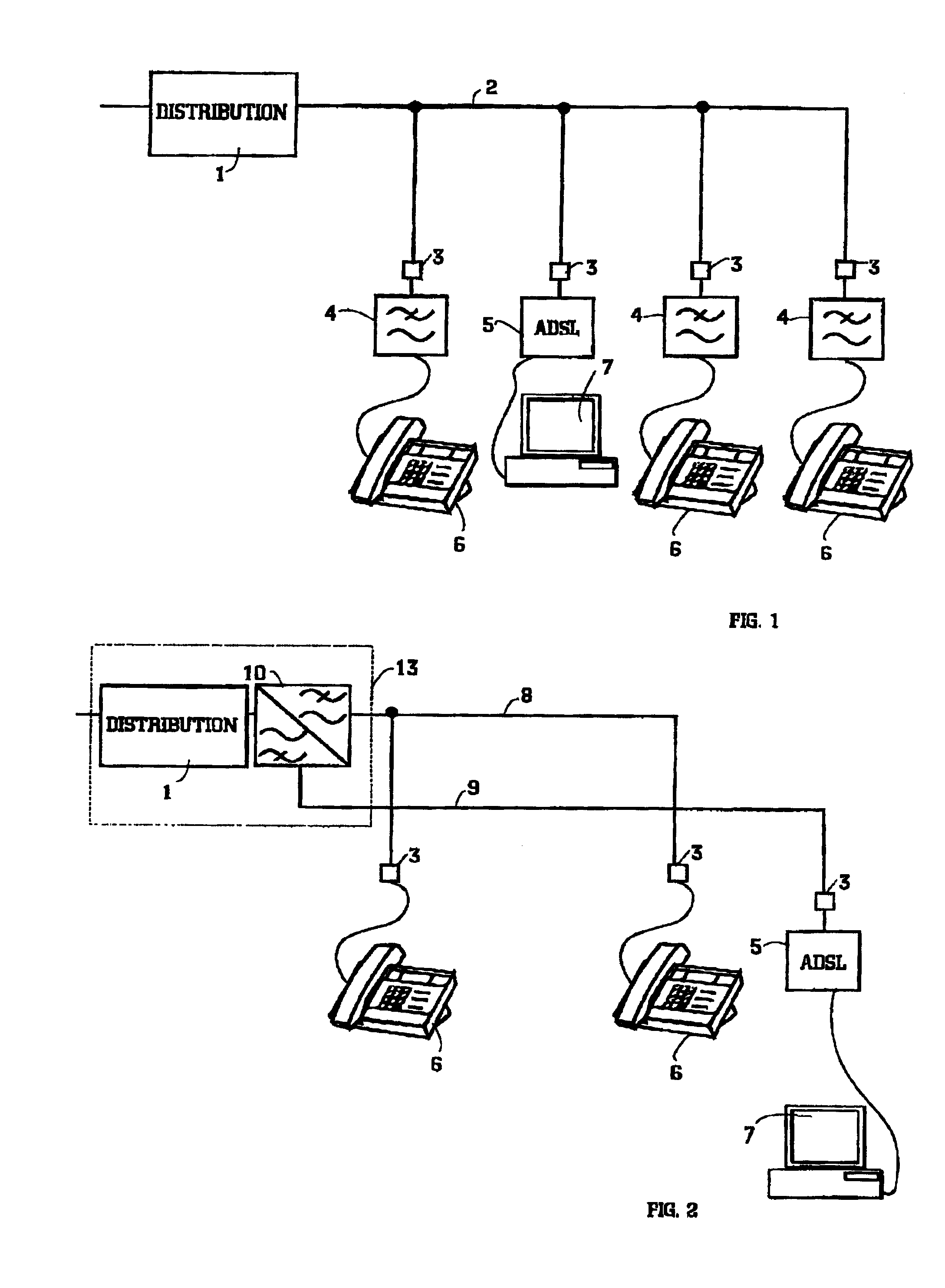
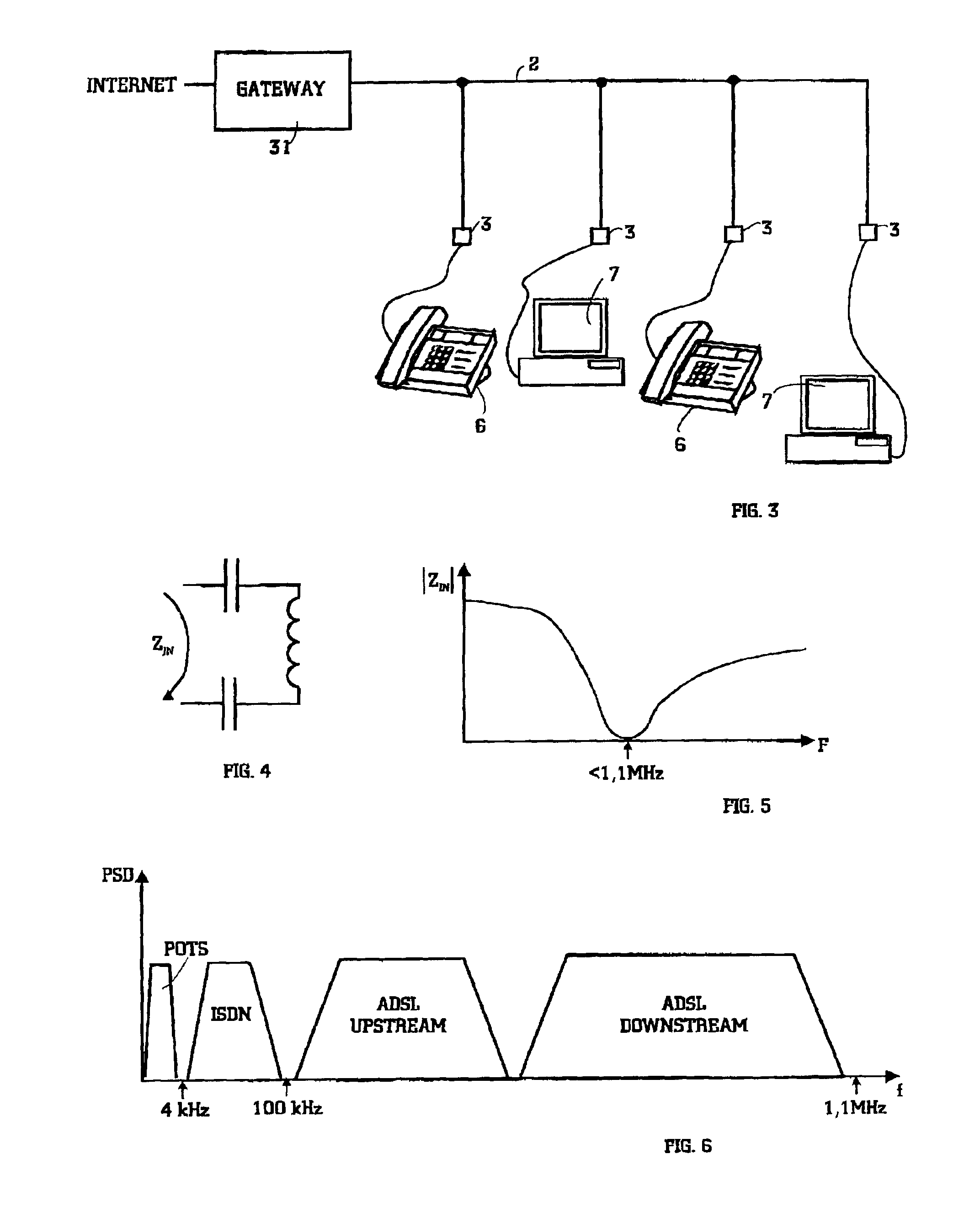
[0031]As mentioned before, usually there is no problem when a subscriber uses a POTS line as a transmission technique to the outside world. But if the subscriber uses an ADSL line as a transmission technique, problems exist. As showed in FIGS. 1 and 2, the computer (and another device), which uses ADSL, is connected to the ADSL modem, which in turn is connected to the telephone socket. POTS terminals are behind low-pass filters. When it is desired to connect the computers together forming a LAN inside the customer's premise, a new frequency range becomes apparent, namely the frequency range of the LAN. In this context, primarily the LAN of HPNA is described. The frequency range of HPNA is about 4-10 MHz. So it is above the frequency ranges of POTS and ADSL as can seen in FIG. 6. So, there are 3 different types of signals in a distribution network, which should be kept separate from the terminals or stations of each other signal type.

[0032]FIG. 7 shows an example of an arrangement ac...


PUM


Abstract

This invention relates to LANs at a customers' premise, especially to the HomePNA technique. The idea of the invention is that voice band terminals and HomePNA (HPNA) stations are hidden from a distribution network by a band division filter in a way that performance of ADSL is not degraded by presence of an HPNA LAN. The band division filter incorporates two subfilters: a POTS filter and an HPNA filter. The latter implements a band stop function maximizing insertion loss at the ADSL band The band division filter can be installed to needed telephone sockets.

Description

FIELD OF THE INVENTION[0001]This invention relates to LANs at customers' premises, especially to the HomePNA technique. More particularly, the invention relates to the separation of signals at LAN of a DSL (Digital Subscriber Line) subscriber.BACKGROUND OF THE INVENTION[0002]The need of data transmission capacity has grown remarkably during the last years. Since most subscriber lines are twisted pair cable, originally designed for voice transmission, new techniques have been developed to increase the capacity of subscriber lines for satisfying continually growing demands. Different DSL (Digital Subscriber Line) techniques even reach transmission speeds of several Mbit / s. Especially, ADSL (Asymmetric Digital Subscriber Line) has become popular.[0003]There are some problems in the ADSL technique. Pair lines considerably attenuate the signals on ADSL frequencies (25-1100 kHz), when the attenuation is at the strongest level at the high frequency end of the bandwidth. The attenuation als...

Claims


Application Information

Patent Timeline
IPC IPC(8): H04Q11/04
CPCH04Q11/0421H04Q2213/13039H04Q2213/13093H04Q2213/13096H04Q2213/1319H04Q2213/13196H04Q2213/13302H04Q2213/13305H04Q2213/13389
Inventor ELO, HARRI
Owner WI LAN INC
Learn More