
Tamper resistant magnetic contact apparatus for security systems

Inactive Publication Date: 2005-11-08
ADEMCO INC
View PDF6 Cites 44 Cited by
  • Summary
  • Abstract
  • Description
  • Claims
  • Application Information

AI Technical Summary

Benefits of technology

[0027]A further object of the invention is to provide an alarm contact apparatus that can

Problems solved by technology

Thieves and intruders of increasing sophistication continue to challenge the peaceful security of businesses and homes alike.
Because security personnel cannot be present at all potential points of entry to a structure, effective security systems require accurate indicators of the movement of doors and windows and other points of entry.
One deficiency with conventional magnetic proximity switches is that the permanent actuating magnets must be precisely positioned with respect to the reed switch, thereby requiring periodic adjustments to avoid false alarms or an ineffective system.
Consequently, regular adjustments must be made as a result of seasonal changes in temperature and humidity, as well as frequent use of the door or window that may lead to misalignment of the permanent magnet and switch.
Misalignment may result in false alarms as well as unscheduled service calls for manual realignment of the switch or magnet.
Another deficiency of conventional magneticall

Method used


Image

  • Tamper resistant magnetic contact apparatus for security systems
  • Tamper resistant magnetic contact apparatus for security systems
  • Tamper resistant magnetic contact apparatus for security systems

Examples


Embodiment Construction

[0040]Referring more specifically to the drawings, for illustrative purposes the present invention is embodied in the apparatus generally shown in FIG. 1 through FIG. 10 wherein like references denote like parts. It will be appreciated that the apparatus may vary as to configuration and as to details of the parts without departing from the basic concepts as disclosed herein.

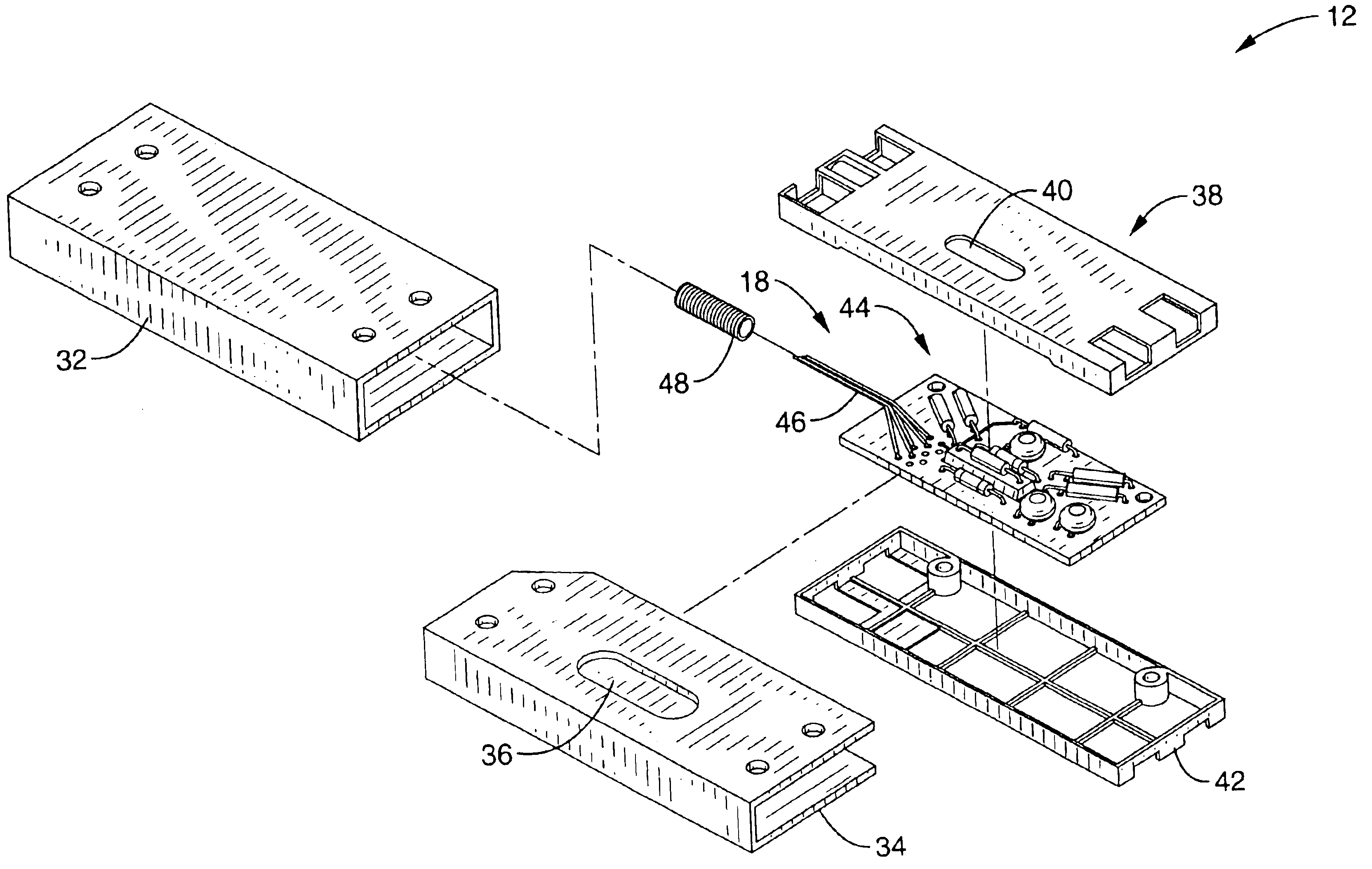
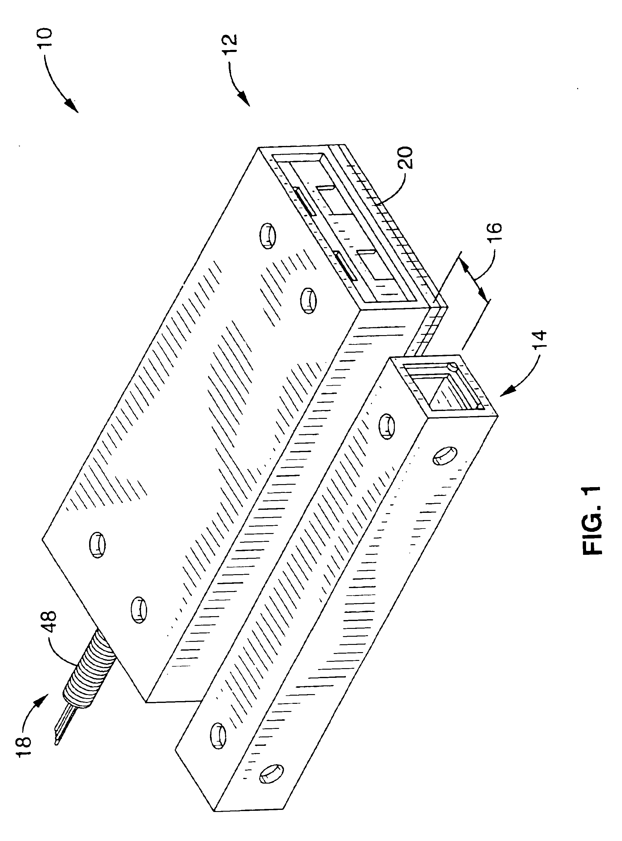
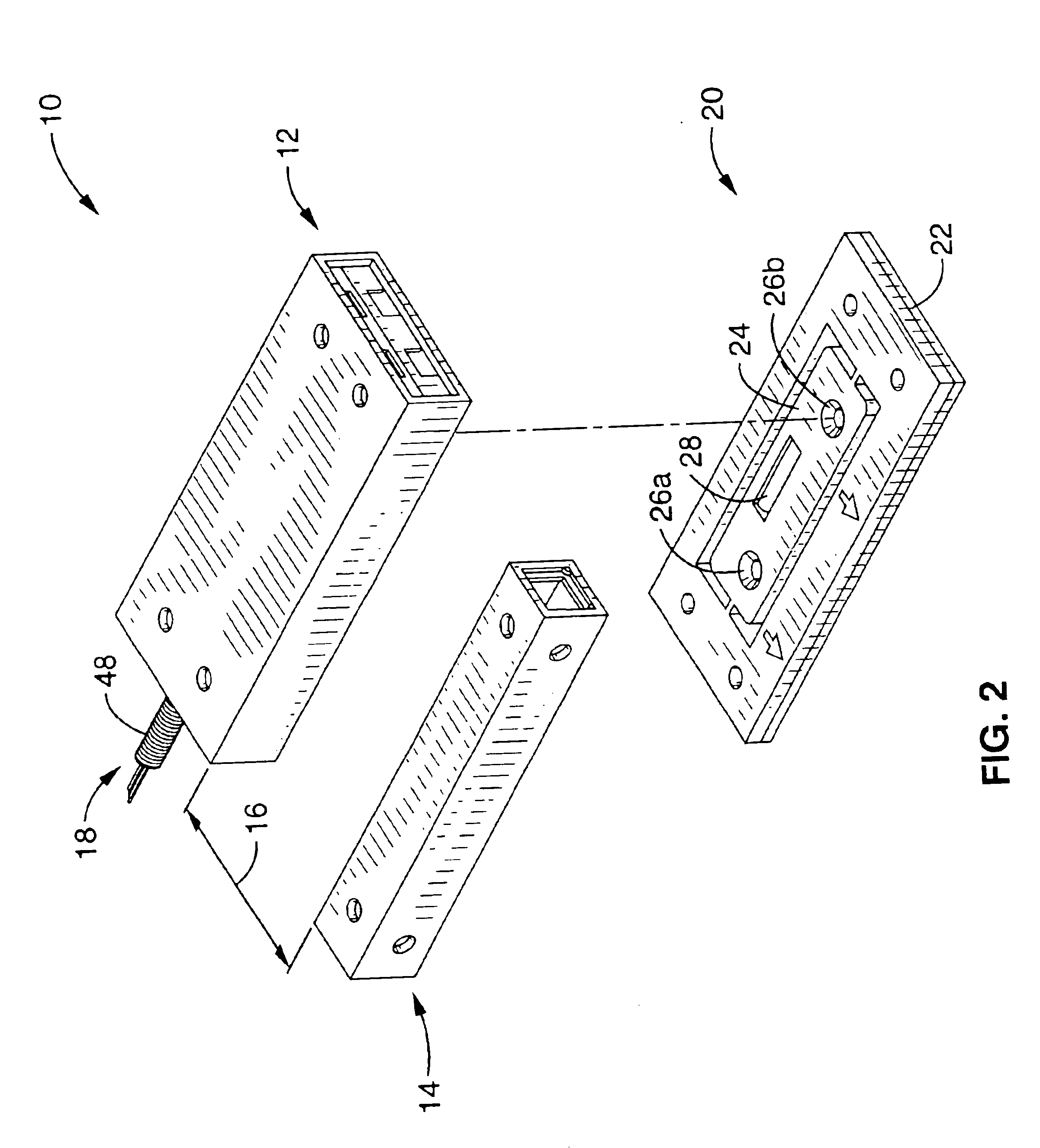
[0041]Referring now to FIG. 1, the high security alarm sensor apparatus 10 of the present invention is generally shown. The apparatus has a sensor unit 12 and a cooperating actuator unit 14, each of which is mounted in a predetermined position with respect to each other on points of entry to a building such as a door or window. The sensor unit 12 has an armored alarm control cable 18 that is preferably electrically connected to a central alarm control panel (not shown). It will be seen that whenever the actuator unit 14 is placed in the proper proximity 16 to the sensor unit 12, the sensor unit remains in a guard...


PUM


Abstract

A tamper resistant magnetic contact switch apparatus for alarm systems that has a plurality of magnetic reed switches configured in a logic circuit and a magnetic pack for actuation. A magnetic shield disposed around the switches defines an actuation zone. In combination with the magnetic shield preventing magnetic fields from reaching the switches from locations outside the actuation zone, the magnet pack activates two of the five switches when positioned within the actuation zone to complete the logic circuit. The magnet pack does not, however, activate any of the other switches. If any of the other three switches are activated, or if either of the two activated switches are deactivated, the logic circuit is broken and the alarm circuit is activated.

Description

CROSS-REFERENCE TO RELATED APPLICATIONS[0001]This application claims priority from U.S. provisional application Ser. No. 60 / 323,988 filed on Sep. 14, 2001, incorporated herein by reference.STATEMENT REGARDING FEDERALLY SPONSORED RESEARCH OR DEVELOPMENT[0002]Not ApplicableREFERENCE TO A COMPUTER PROGRAM APPENDIX[0003]Not ApplicableBACKGROUND OF THE INVENTION[0004]1. Field of the Invention[0005]This invention relates generally to high security, tamper resistant contact systems and more particularly to a logic circuit including magnetically actuated sensors that are resistant to foreign magnetic fields and that do not require custom tuning for monitoring door or window openings or the like as part of an electrically monitored physical security system.[0006]2. Description of the Background Art[0007]Thieves and intruders of increasing sophistication continue to challenge the peaceful security of businesses and homes alike. Because security personnel cannot be present at all potential poi...

Claims


Application Information

Patent Timeline
IPC IPC(8): G08B29/00G08B29/04G08B13/08G08B13/02H01H36/00
CPCG08B13/08G08B29/046H01H36/0046
Inventor BUCKLEY, MARK C.
Owner ADEMCO INC
Learn More