Torsional vibration damper, especially a dual-mass flywheel

a technology of torsional vibration and damper, which is applied in the direction of yielding couplings, mechanical devices, couplings, etc., can solve the problems of fractures and much greater loads, and achieve the effect of prolonging service li

Inactive Publication Date: 2005-11-08
ZF SACHS AG
View PDF11 Cites 11 Cited by
  • Summary
  • Abstract
  • Description
  • Claims
  • Application Information

AI Technical Summary

Benefits of technology

[0006]The task of the present invention is to improve a torsional vibration damper of the basic type in question in such a way that it has a longer service life.
[0008]The inventors discovered that fatigue fractures are attributable to the fact that, when excessive loads are imposed on the torsional vibration damper according to the state of the art, only one of the spring arrangements comes to rest against a stop, whereas the other spring arrangement still allows the secondary side to rotate relative to the primary side. According to the state of the art, the spring arrangement which comes to rest against a stop is therefore subjected to much greater loads than the other spring arrangement and therefore also fractures sooner.
[0009]As a result of the design according to the invention, however, an excessive load, when it occurs, is distributed over both spring arrangements, so that the service life of the torsional vibration damper can be increased.
[0011]The spring arrangements usually have spring elements and guide elements, on which the spring elements are supported. A design of this type is especially durable and works with very low friction. The guide elements in this case comprise at least outer guide elements, which are supported on support areas on the primary side and / or on driver elements on the secondary side.

Problems solved by technology

According to the state of the art, the spring arrangement which comes to rest against a stop is therefore subjected to much greater loads than the other spring arrangement and therefore also fractures sooner.

Method used


Image

  • Torsional vibration damper, especially a dual-mass flywheel
  • Torsional vibration damper, especially a dual-mass flywheel
  • Torsional vibration damper, especially a dual-mass flywheel

Examples


Embodiment Construction

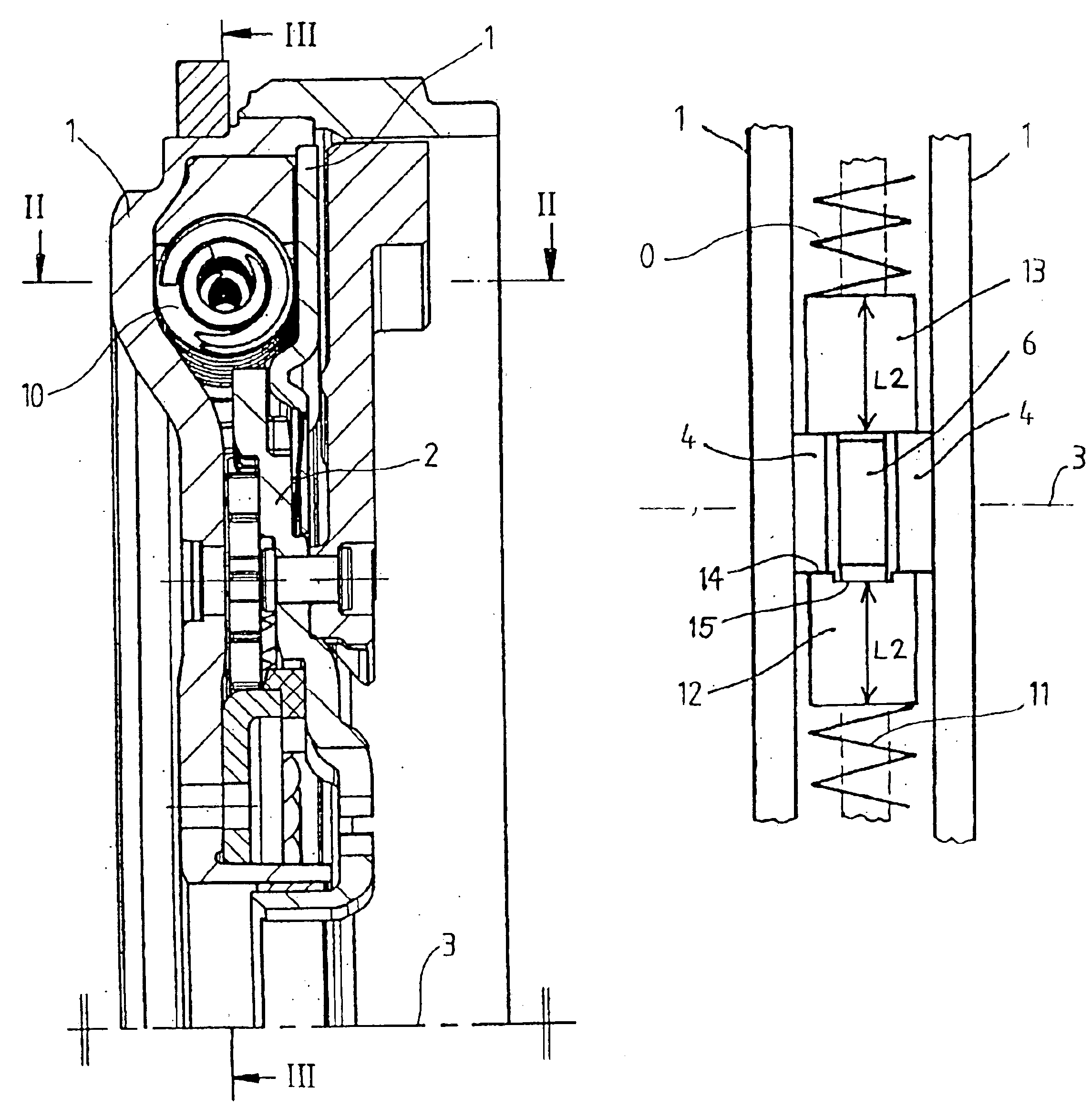
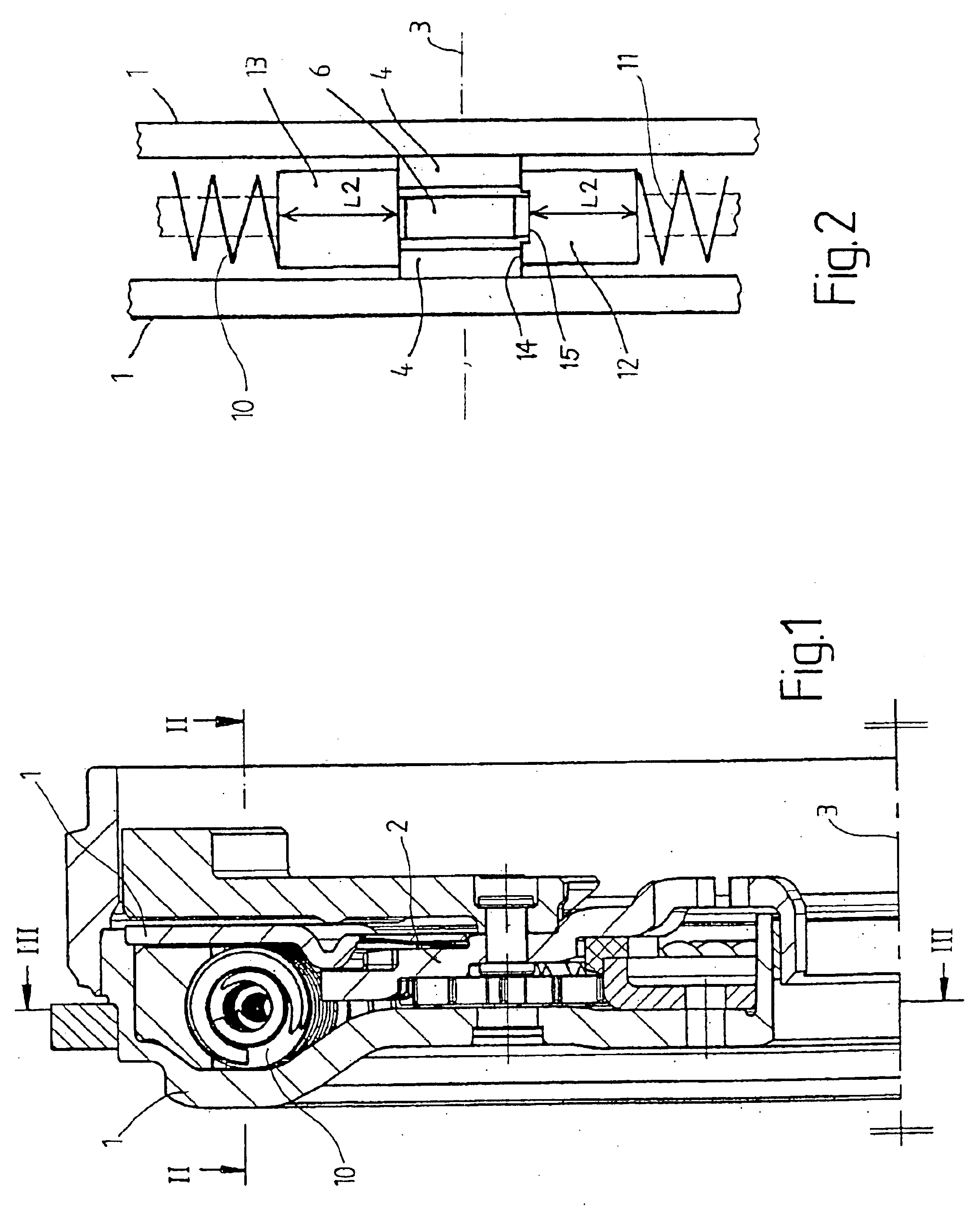
[0033]According to FIGS. 1 and 2, a dual-mass flywheel as an example of a torsional vibration damper has a primary side 1 and a secondary side 2. The secondary side 2 is able to turn around an axis of rotation 3 relative to the primary side 1.

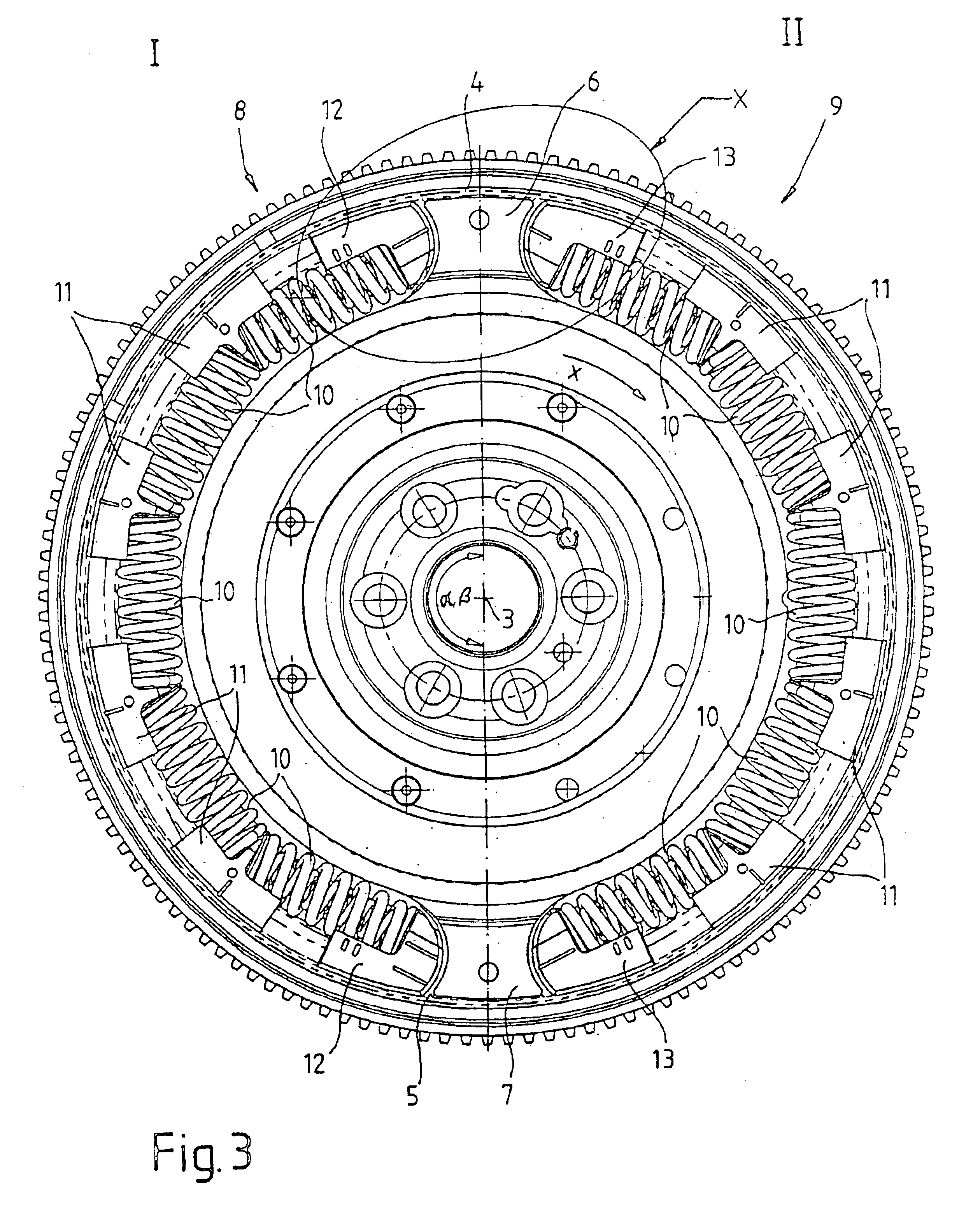
[0034]According to FIGS. 2 and 3, support areas 4, 5 are provided on the primary side 1. The support areas 4, 5 are offset with respect to each other by a support area angle α of 180°. Driver elements 6, 7 are attached to the secondary side 2, which are offset from each other by a driver element angle β, which is also 180°. The support area angle a and the driver element angle β are therefore equal to each other.

[0035]Spring arrangements 8, 9 have, according to FIG. 3, spring elements 10, inner guide elements 11, and outer guide elements 12, 13. The spring elements 10 are supported by the guide elements 11, 12, 13. By way of the outer spring guide elements 12, 13, the spring arrangements 8, 9 are also supported on the support areas 4, 5 and on ...


PUM


Abstract

A torsional vibration damper, especially a dual-mass flywheel, has a primary side and a secondary side, which is free to rotate around an axis of rotation relative to the primary side. Starting from a rotation in a direction of rotation around a forward base angle (γ), a forward base spring arrangement exerts a forward base restoring force on the secondary side. Starting from rotation around a forward auxiliary angle (δ), which is greater than the forward base angle (γ), a forward auxiliary spring arrangement exerts an additional forward auxiliary restoring force. Upon rotation around a forward limit angle (ε), both spring arrangements come to a stop together.

Description

BACKGROUND OF THE INVENTION[0001]1. Field of the Invention[0002]The present invention pertains to a torsional vibration damper, especially to a dual-mass flywheel, with a primary side and a secondary side, where the secondary side is free to rotate relative to the primary side around an axis of rotation; where, starting from a rotation in one rotational direction around a forward base angle, a forward base spring arrangement exerts a forward base restoring force on the secondary side; where, starting from a rotation in the rotational direction around a forward auxiliary angle, a forward auxiliary spring arrangement also exerts a forward auxiliary restoring force on the secondary side; and where the forward auxiliary angle is larger than the forward base angle.[0003]2. Description of the Related Art[0004]Torsional vibration dampers are used especially between the crankshaft of an internal combustion engine and the transmission to keep the torsional vibrations caused by the internal c...

Claims


Application Information

Patent Timeline
Patent Type & Authority Patents(United States)
IPC IPC(8): F16F15/134F16F15/131
CPCF16F15/13438F16F15/13492
Inventor ZOTTMANN, MICHAELKLEIFGES, JURGENSCHIERLING, BERNHARDMANGER, ALEXANDER
Owner ZF SACHS AG
Why Eureka
Try Eureka