
Device to detect pressure in an x-ray tube

a technology of x-ray tube and pressure sensor, which is applied in the direction of vacuum gauge using ionisation effect, x-ray tube gas filling, electric discharge tube, etc., can solve the problems of reducing the voltage stability of the tube first, unsatisfactory internal pressure rise, and failure of the x-ray tube, etc., to achieve simple and cost-effective effect of implementation

Active Publication Date: 2005-11-01
SIEMENS HEALTHCARE GMBH
View PDF7 Cites 3 Cited by
  • Summary
  • Abstract
  • Description
  • Claims
  • Application Information

AI Technical Summary

Benefits of technology

[0006]An object of the present invention to provide a method for measuring the pressure in an x-ray tube that avoids the disadvantages according to the prior art. In particular, it is an object to provide an optimally simply and cost-effectively implementable method to detect the pressure prevalent in an x-ray tube.
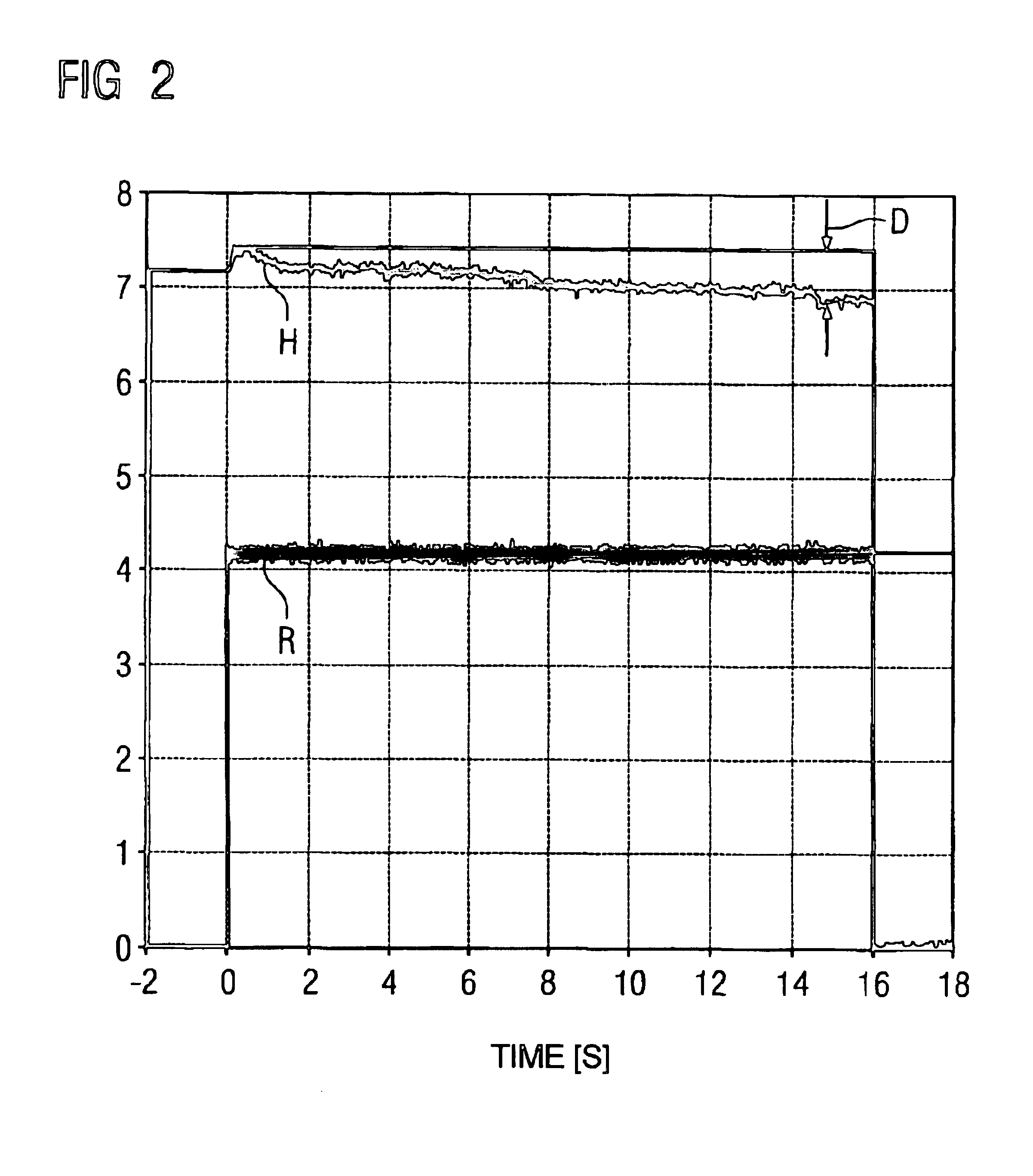
[0008]The above method can be implemented without great expenditure. In particular no structural change to the x-ray tube is necessary. By monitoring the temporal change of the heater current in comparison to the applied x-ray voltage or to the applied tube voltage, a decrease of the heater current is obtained in the event of a pressure drop in the x-ray tube, for example given constant tube current. The difference resulting from this is a measure of the pressure drop in the x-ray tube. A value indicating a voltage stability and / or a remaining lifespan can be determined and provided from the value representing the pressure in the x-ray tube. In particular, a determination and display of a remaining lifespan enables an early recognition of a failure of the x-ray tube. The risk of an unforeseen failure of an x-ray tube is reduced.

Problems solved by technology

A problem in x-ray tubes is that, due to a leakage, an undesired rise in the internal pressure can occur.
As a result, generally a reduction of the tube voltage stability first occurs and later a failure of the x-ray tube can occur.
An unforeseen failure of an x-ray tube in a running hospital operation causes replacement expense and downtime costs.

Method used


Image

  • Device to detect pressure in an x-ray tube
  • Device to detect pressure in an x-ray tube
  • Device to detect pressure in an x-ray tube

Examples


Embodiment Construction

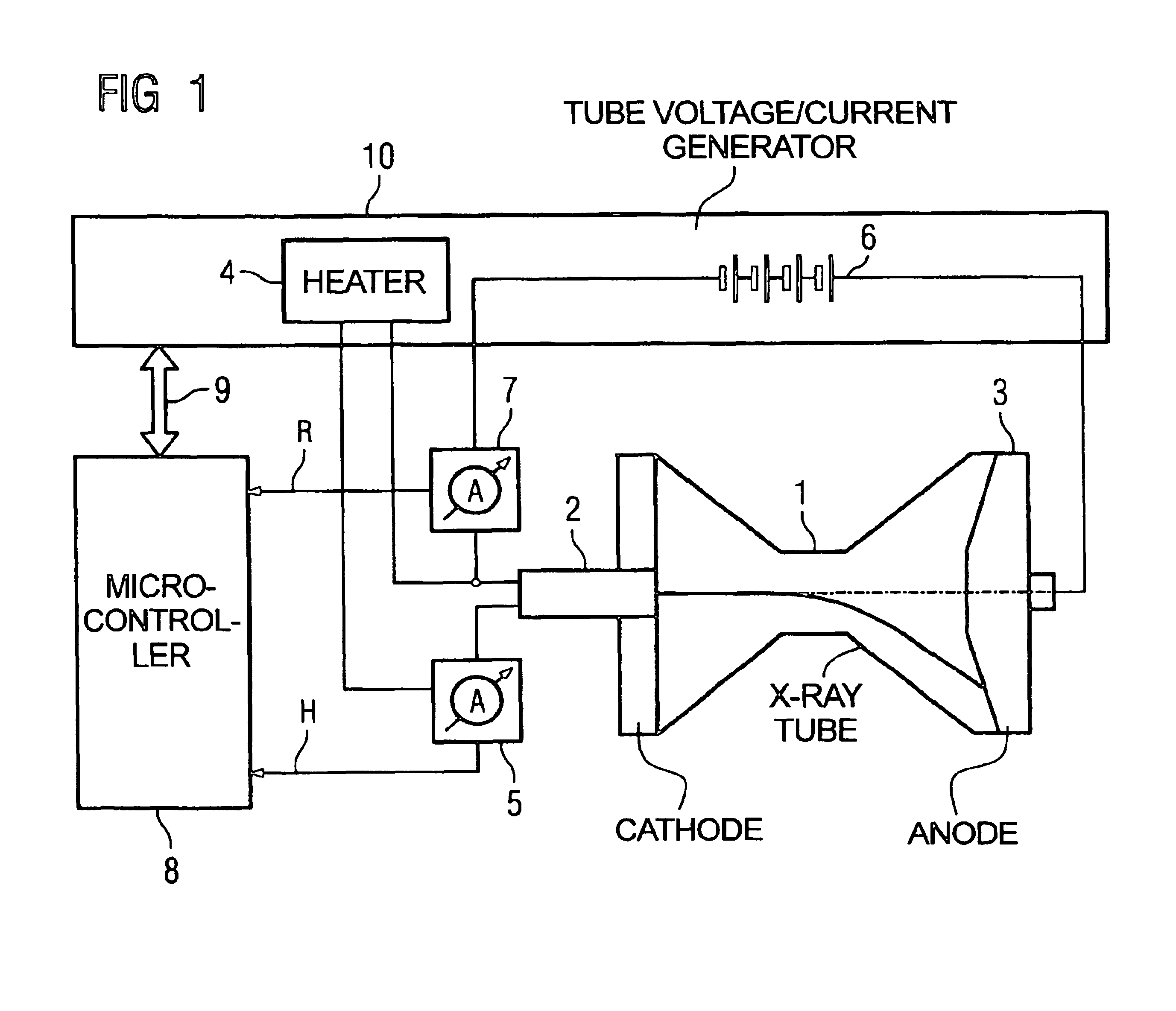
[0015]In the x-ray system shown in FIG. 1, an x-ray tube has a cathode 2 and an anode 3. A heater 4 is connected with the cathode 2 upon activation of a first device 5 for current measurement. A high-voltage source 6 is connected with the cathode 2 and the anode 3 upon interposition of a second device 7 for current measurement. The devices 5, 7 for current measurement are additionally connected to a microcontroller that via an interface 9 is connected with a process computer (not shown) of a tube voltage / current generator 10 that includes the heater 4 and the voltage source 6.

[0016]By means of the heater 4, the cathode 2 is heated so as to emit electrons. The applied heater current is measured with the first device 5 for current measurement. The measurement values are provided to the microcontroller 8. The x-ray voltage applied between the cathode 2 and the anode 3 is generated by the high-voltage generator 6. The x-ray current drop is measured by the second device 7 for current mea...


PUM


Abstract

In a method to detect the pressure in an x-ray tube having a cathode of the x-ray tube that is heated with a heater current, and wherein electrons are accelerated between the cathode and an anode by an applied x-ray tube voltage, the heater current is measured, a tube current corresponding to the tube -ray voltage is measured, the difference between the measured heater current and the measured tube current is determined or the temporal change of the measured heater current or of the measured tube current is determined, the difference or the temporal change is compared with predetermined calibration values, and a value representing the pressure in the x-ray tube is determined from the comparison.

Description

BACKGROUND OF THE INVENTION[0001]1. Field of the Invention[0002]The present invention concerns a method to detect pressure in an x-ray tube.[0003]2. Description of the Prior Art[0004]A problem in x-ray tubes is that, due to a leakage, an undesired rise in the internal pressure can occur. As a result, generally a reduction of the tube voltage stability first occurs and later a failure of the x-ray tube can occur. An unforeseen failure of an x-ray tube in a running hospital operation causes replacement expense and downtime costs.[0005]From United States Publication Application 2002 / 0185593, an ion mobility spectrometer is known in which a particular control electrode disposed opposite the cathode is provided to measure the pressure in an x-ray tube. The pressure in the x-ray tube is measured by a fault current flowing between the control electrode and the cathode.SUMMARY OF THE INVENTION[0006]An object of the present invention to provide a method for measuring the pressure in an x-ray...

Claims


Application Information

Patent Timeline
IPC IPC(8): H01J35/02H01J35/00G01L21/30
CPCG01L21/30H01J35/02
Inventor DEURINGER, JOSEFFREUDENBERGER, JORGSCHARDT, PETERSCHILD, MARKUS
Owner SIEMENS HEALTHCARE GMBH
Learn More