
Method and apparatus for non-contact thickness measurement

a non-contact, thickness measurement technology, applied in the direction of electrical/magnetic thickness measurement, instruments, caliper-like sensors, etc., can solve the problems of inability to test, excessive delay, and high cost, and the operator of the equipment and parts of the facility in which a product is painted may be idl

Inactive Publication Date: 2005-11-01
THE BOEING CO
View PDF13 Cites 8 Cited by
  • Summary
  • Abstract
  • Description
  • Claims
  • Application Information

AI Technical Summary

Benefits of technology

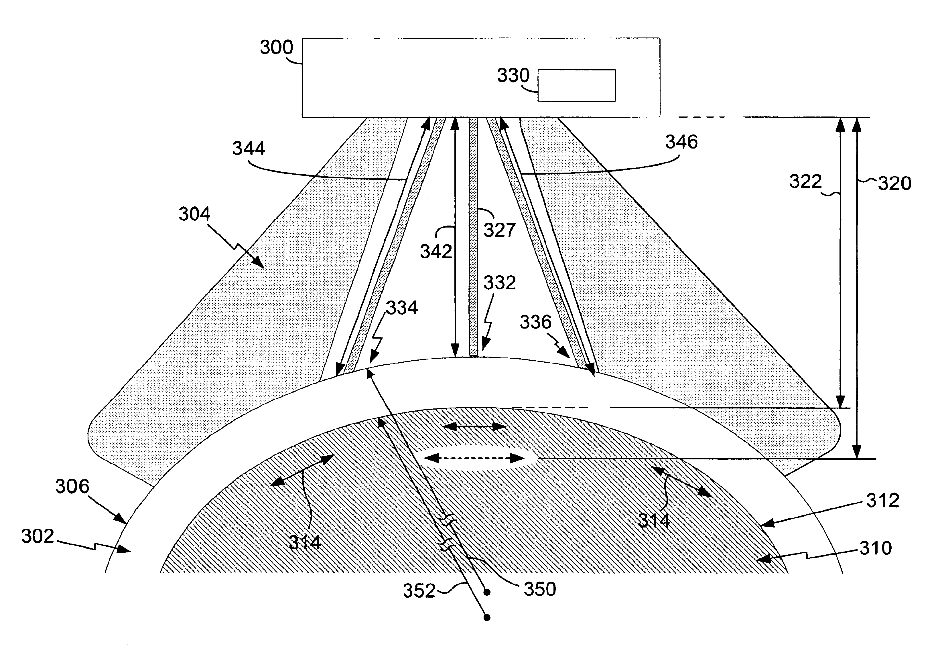
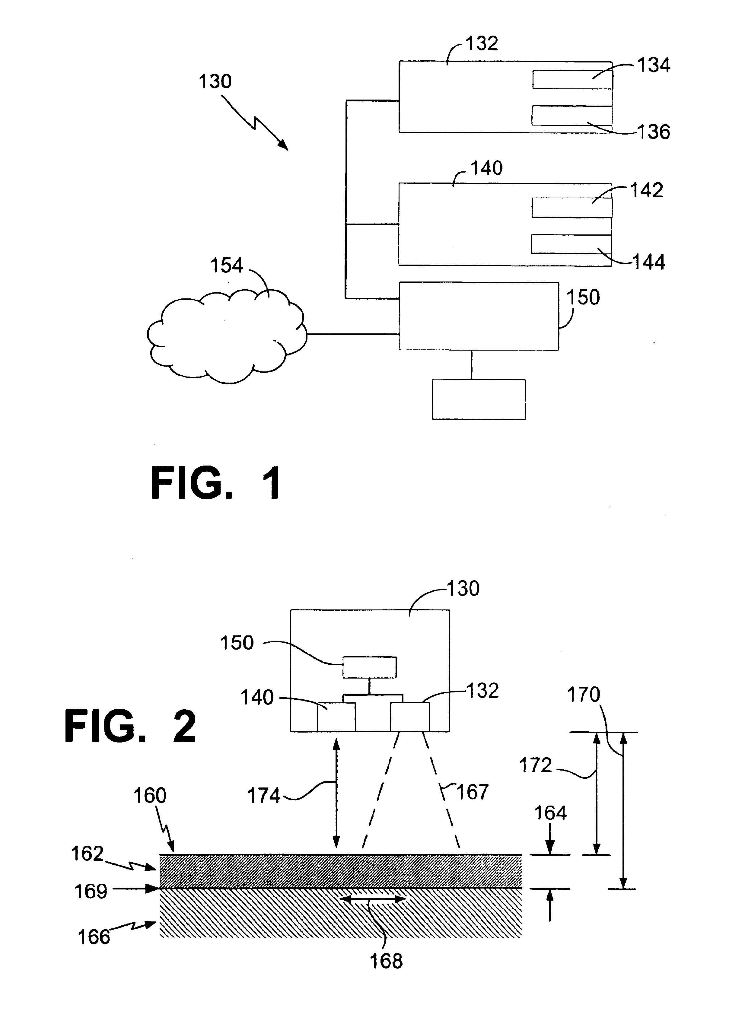
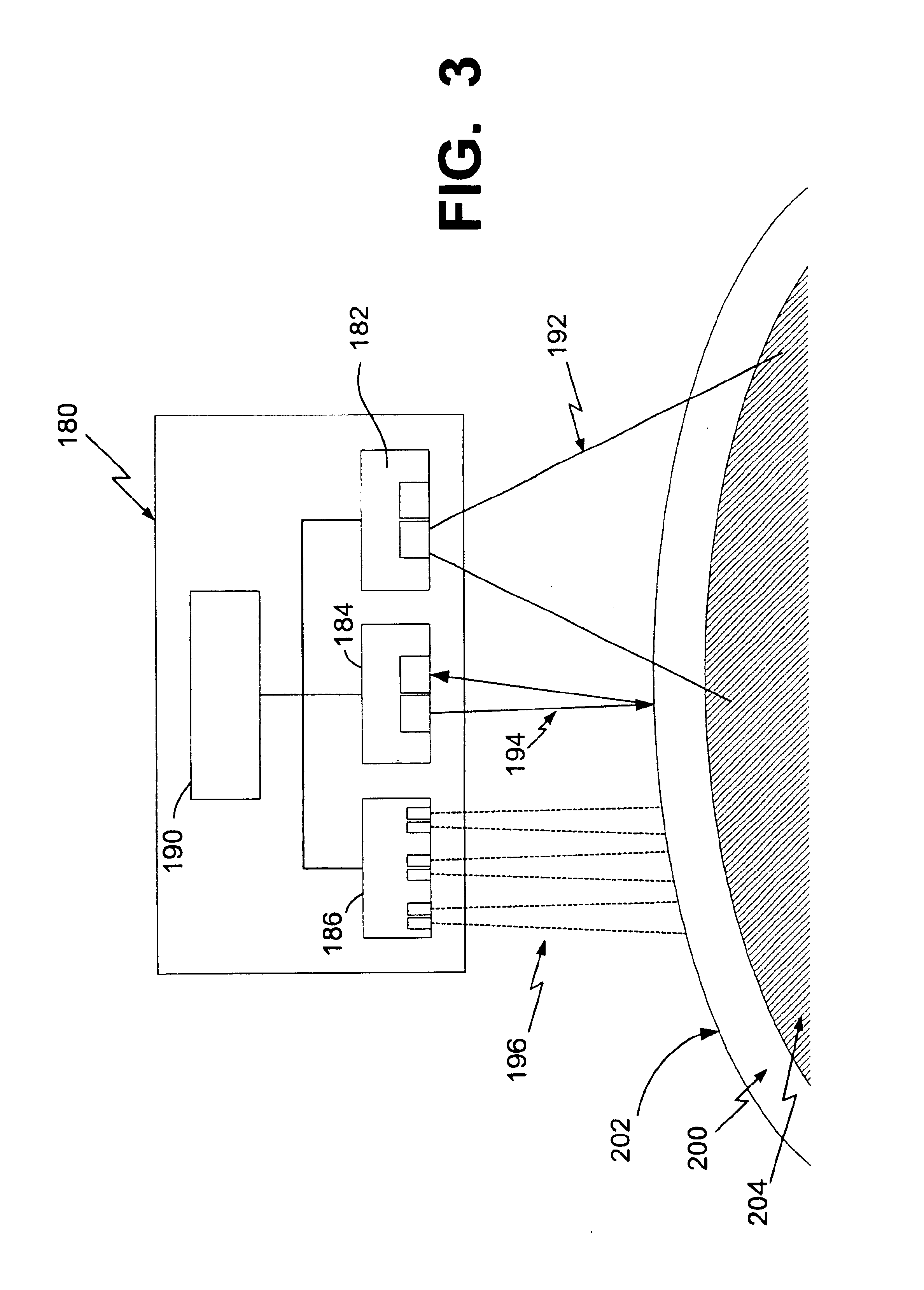
The present invention provides an apparatus, system, and method for measuring the thickness of a layer and changes in layer thickness. The apparatus includes a light source, light beam detector, eddy current field generator, eddy current detector, and processor. The apparatus can also include a proximity sensor to detect the distance between the apparatus and the surface of the layer. The method involves inducing an eddy current in the substrate, detecting the induced eddy current, determining the distance to the induced eddy current, generating a laser beam, detecting the laser beam reflected from the layer surface, and determining the thickness of the layer using the distance to the induced eddy current and the distance to the surface. The technical effects of the invention include improved accuracy and non-contact measurement of layer thickness.

Problems solved by technology

Waiting for paint to dry in order to measure the thickness of the paint layer can result in excessively long delays and be extremely costly.
Some of the equipment for painting, operators of the equipment and parts of the facility in which a product is painted may be idle during this waiting period.
This test is not very reliable.
Further, the shim damages the paint surface which has to be repaired.

Method used


Image

  • Method and apparatus for non-contact thickness measurement
  • Method and apparatus for non-contact thickness measurement
  • Method and apparatus for non-contact thickness measurement

Examples


Embodiment Construction

[0023]The following description of the presently contemplated best mode of practicing the invention is not to be taken in a limiting sense, but is made merely for the purpose of describing the general principles of the invention. The scope of the invention should be determined with reference to the claims.

[0024]The present invention provides a method and apparatus for measuring the thickness of layers or films on a substrate. The present method and apparatus additionally are capable of measuring recesses in a layer (e.g., scratches, grooves, etc.) and / or layer thickness variations. Further, the present invention further provides for a method and apparatus to determine the thickness, depth and / or variation of a layer without having to contact the layer. For example, the present invention can measure the thickness of a layer while the layer is still wet. As such, the thickness of the layer can be determined without causing damage to the layer or putting blemishes in the layer. The pre...


PUM


Abstract

The present invention provides a method and apparatus for use in measuring a thickness of a layer and / or variations in layer thickness for layers that are flat, curved or have curves. The apparatus comprises a light source to generate a light beam, a light beam detector to detect at least a portion of the light beam reflected, an eddy current field generator that induces an eddy current, an eddy current detector to detect the induced eddy current and a processor coupled with the light source, light detector, eddy current field generator and eddy current detector, wherein the processor controls the light detector, eddy current field generator and eddy current detector. A radial characteristic of a region of the surface can be determined, a scaling factor can be determined based on the radial characteristic and a measured distance can be scaled based on the scaling factor in determining a thickness.

Description

BACKGROUND OF THE INVENTION[0001]The present invention relates generally to non-contact thickness measurements, and more particularly to non-contact layer thickness measurements and layer thickness variations.[0002]It is sometimes advantageous to measure a thickness of a wet film or layer. For example, when applying paint to a surface it can be advantageous to know the thickness of the paint. Previously, the thickness was not measured until the paint was dry. This way the paint was not damaged or blemished. Waiting for paint to dry in order to measure the thickness of the paint layer can result in excessively long delays and be extremely costly. Some of the equipment for painting, operators of the equipment and parts of the facility in which a product is painted may be idle during this waiting period.[0003]In some instances, the paint is measured when the paint is wet. These previous techniques required the wet paint to be touched. For example, a shim or other similar structure can ...

Claims


Application Information

Patent Timeline
Patent Type & Authority Patents(United States)
IPC IPC(8): G01B11/02G01B7/06G01B11/06G01B11/28G01R33/12
CPCG01B7/105G01B11/026G01B2210/42G01B2210/40
Inventor CATON, LINDSEY M.SERGOYAN, EDWARD G.
Owner THE BOEING CO
Learn More