
Woodwork removal device

a removal device and woodwork technology, applied in metal-working equipment, metal-working equipment, construction, etc., can solve the problems of wasting time and money, woodwork is brittle and fastened with a surprising number of larger-than-necessary nails, so as to facilitate the insertion of the tapered end, the effect of widening the width

Inactive Publication Date: 2005-11-01
ANIBAS KEVIN J
View PDF12 Cites 13 Cited by
  • Summary
  • Abstract
  • Description
  • Claims
  • Application Information

AI Technical Summary

Benefits of technology

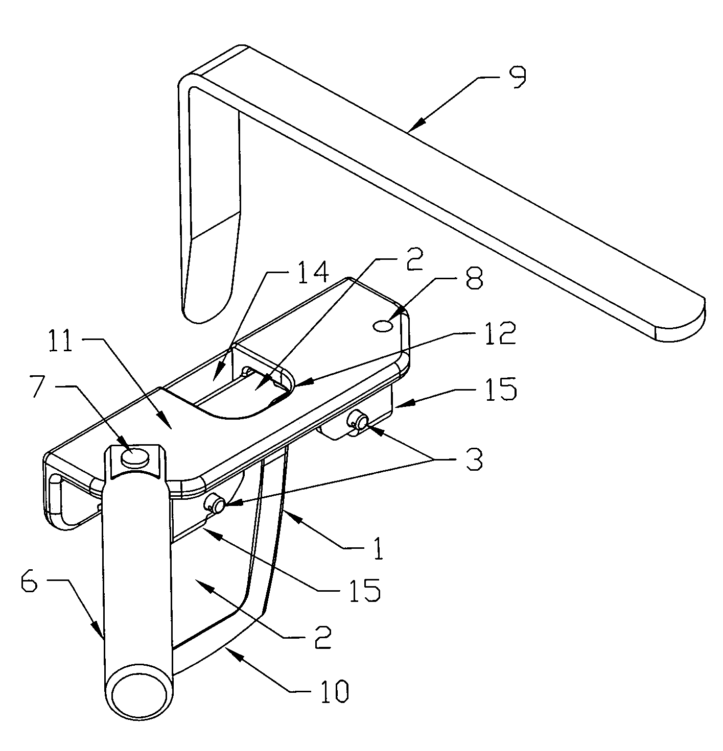
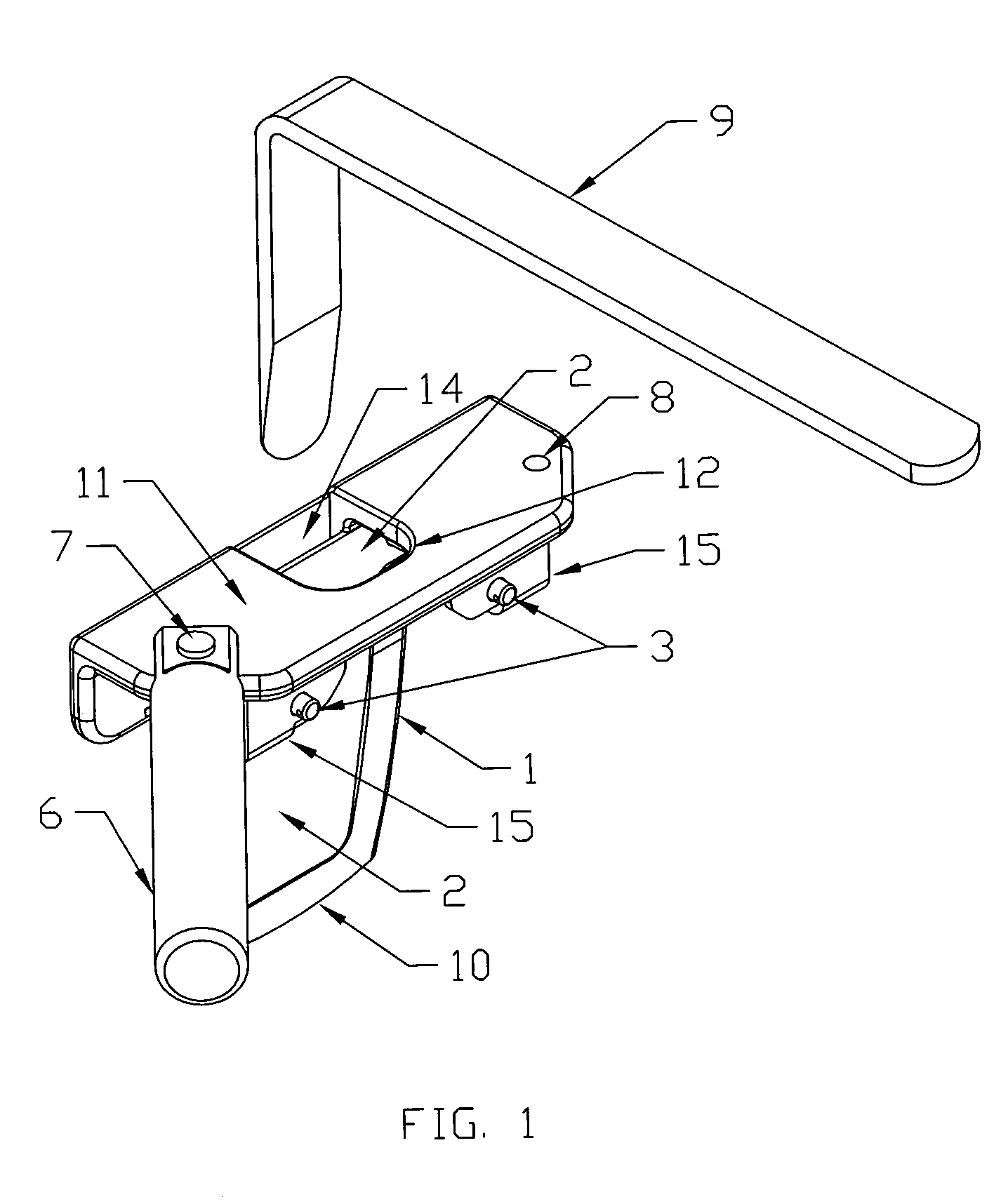
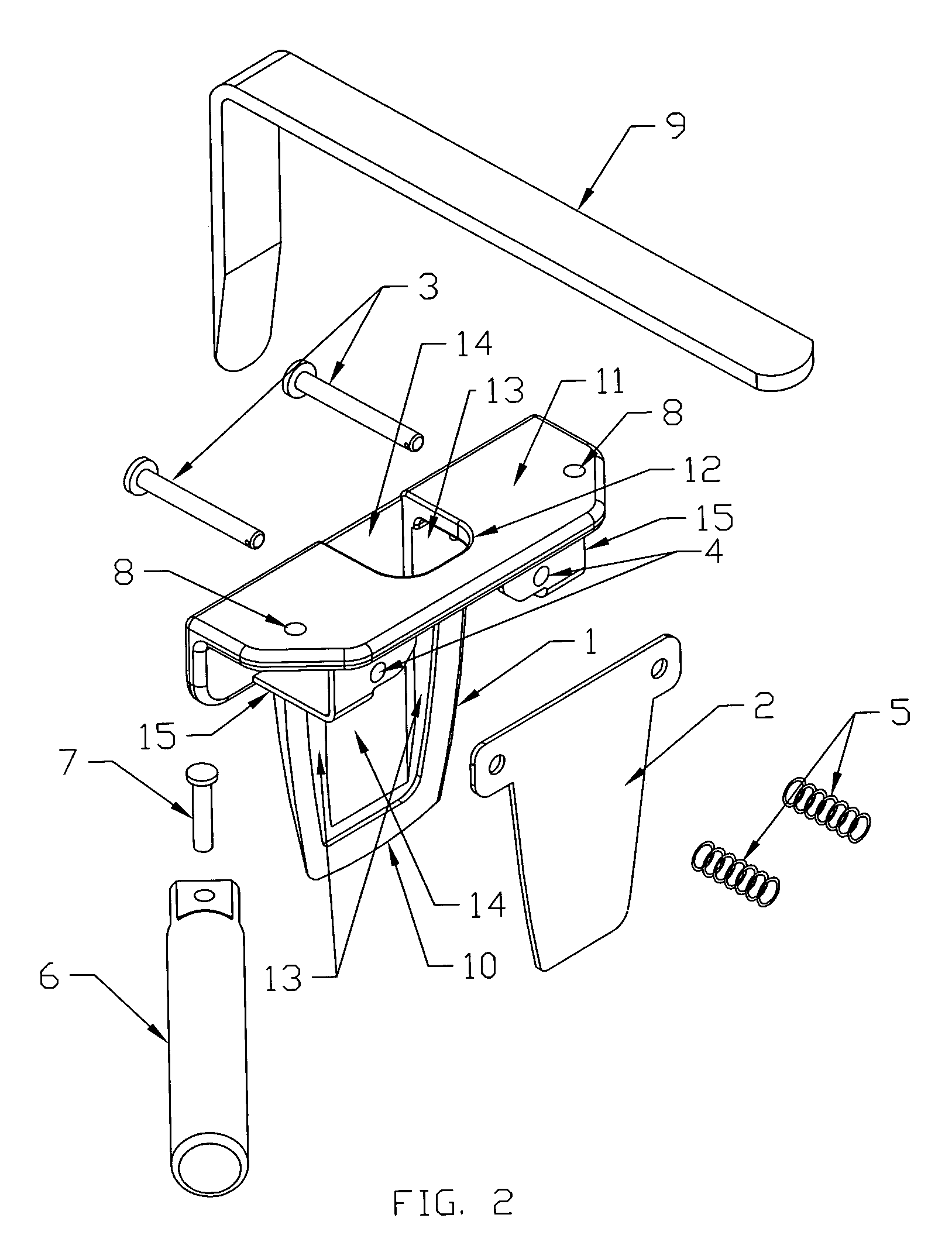
[0011]In a preferred embodiment of the invention, the device for removal of woodwork or trim from a wall includes a planar tool body member having a top portion, a center portion, and a bottom portion. The bottom portion tapers to a hard edge, the center portion includes, in register, a lever pocket and a lifter plate pocket, and the top portion includes a striking surface extending perpendicularly from one side of the planar tool body member. The striking surface includes an aperture accessing the lever pocket and the lifter plate pocket. A planar lifter plate member is biasedly mounted against the lifter plate pocket of the tool body member. An angled, lever bar member having a cross section greater in width than in thickness is tapered at one end to facilitate insertion of the tapered end into the tool body member lever pocket via the aperture in the striking surface.

Problems solved by technology

Often, especially in older homes, this woodwork is brittle and fastened with a surprising number of larger-than-necessary nails.
Because these tools present hard steel edges and small surface areas to the wall and the woodwork, damage such as gouging, cracking, or scratching is likely.
Time and money are wasted, and the goodwill of the building owner and the trades person is sometimes strained while the damage is repaired.
Historic homes and buildings may have custom or out-of-production woodwork which is no longer available should a section of it be destroyed when being removed.

Method used


Image

  • Woodwork removal device
  • Woodwork removal device
  • Woodwork removal device

Examples


Embodiment Construction

Nomenclature

[0021]1 Planar Tool Body Member[0022]2 Lifter Plate Member[0023]3 Lifter Plate Pin Member[0024]4 Lifter Plate Pin Member Hole[0025]5 Spring Member[0026]6 Handle Member[0027]7 Handle Pin Member[0028]8 Handle Pin Member Hole[0029]9 Lever Bar Member[0030]10 Hard Edge[0031]11 Striking Surface[0032]12 Access Aperture[0033]13 Lifter Plate Pocket[0034]14 Lever Bar Pocket[0035]15 Stop Structure Protecting the Lifter Plate Pins and Springs[0036]16 Section of Woodwork or Trim[0037]17 Wall

Construction

[0038]Although the disclosure hereof is detailed and exact to enable those skilled in the art to practice the invention, the physical embodiments herein disclosed merely exemplify the invention, which may be embodied in other specific structure. The scope of the invention is defined in the claims appended hereto.

[0039]The invention is an assembly for removal of woodwork or trim from the wall of a building. Referring now to FIGS. 1 and 2, several views of the assembly are shown. The ass...


PUM

PropertyMeasurementUnit
widthaaaaaaaaaa
thicknessaaaaaaaaaa
surface areaaaaaaaaaaa

Abstract

Disclosed is a device for removing woodwork and trim from the interior or exterior of buildings. Its function is such that damage to the woodwork, and to the wall from which it is removed, is minimized or eliminated. In operation, the device is first driven between the wall and the woodwork to be removed. A specially shaped bar is then inserted between the base of the device and a spring loaded lifter plate. When this bar is pivoted, the lifter plate is moved away from the base, wedging the woodwork loose. Since a relatively large surface area acts on the wall and the woodwork, gouging or other damage is unlikely. Removed trim pieces may be reinstalled or salvaged for use on other projects.

Description

CROSS-REFERENCE TO RELATED APPLICATION, IF ANY[0001]Not applicable.STATEMENT REGARDING FEDERALLY SPONSORED RESEARCH OR DEVELOPMENT[0002]Not applicable.REFERENCE TO A MICROFICHE APPENDIX, IF ANY[0003]Not applicable.BACKGROUND OF THE INVENTION[0004]1. Field of the Invention[0005]The present invention is a device for removing woodwork and trim from the interior or exterior of buildings.[0006]2. Background Information[0007]This invention applies to removing woodwork and trim from the interior or exterior of buildings with minimal or no damage to the woodwork or to the wall from which it is removed.[0008]Trades people, such as carpenters, electricians, window and door replacement contractors, telephone and cable TV installers, and carpet installers, frequently find it necessary to remove woodwork or trim in the course of their work. Often, especially in older homes, this woodwork is brittle and fastened with a surprising number of larger-than-necessary nails. Common tools for this job ar...

Claims


Application Information

Patent Timeline
Patent Type & Authority Patents(United States)
IPC IPC(8): B23P19/04B25B27/00E04F19/04
CPCB25B27/00E04F19/049Y10T29/53683E04F2019/0409
Inventor ANIBAS, KEVIN J.
Owner ANIBAS KEVIN J
Learn More