
Frying apparatus with closed loop combustion control and method

a technology of combustion control and frying apparatus, which is applied in the direction of combustion types, combustion using lumps and pulverulent fuel, and domestic stoves or ranges, etc. it can solve the problems of difficult cleaning of the fryer tube, the disadvantage of heating the entire fryer including the temperature sensitive wiring and controls, and the disadvantage of the burner adjacent to the exterior side of the fryer . the effect of high efficiency

Inactive Publication Date: 2005-10-25
FRYMASTER CORPTHE
View PDF2 Cites 16 Cited by
  • Summary
  • Abstract
  • Description
  • Claims
  • Application Information

AI Technical Summary

Benefits of technology

[0011]The frying apparatus of the present invention has a fry pot and a combustion burner (combustion chamber / heat exchanger combined) that is disposed to heat cooking fluid contained in the fry pot. By means of a modulated air supply and an orificed or modulated gas supply, an optimum mixture occurs in the combustion burner. One or more sensors sense an operating parameter of the frying apparatus to develop a feedback signal. A control responds to the feed back signal to adjust the air / gas supply for maximum efficiency and clean combustion.
[0013]According to another embodiment of the present invention, a frying apparatus includes a fry pot and a combustion burner. The combustion burner includes a combustion chamber and a heat exchanger with the combustion occurring below the oil line. The combustion burner is removably disposed in the fry pot below the cooking fluid level. A flue extends from the heat exchanger out of the cooking fluid. The combustion burner is disposed for motion between a cooking position where it is disposed in the cooking fluid and a removed position outside the cooking fluid for ease of cleaning.

Problems solved by technology

The disposition of the burner adjacent the exterior sides of the fry pot has the disadvantage of heating the entire fry pot including the temperature sensitive wiring and controls.
The tube fryer is also difficult to clean due to the tubes that are permanently installed in the fry pot.

Method used


Image

  • Frying apparatus with closed loop combustion control and method
  • Frying apparatus with closed loop combustion control and method
  • Frying apparatus with closed loop combustion control and method

Examples


Embodiment Construction

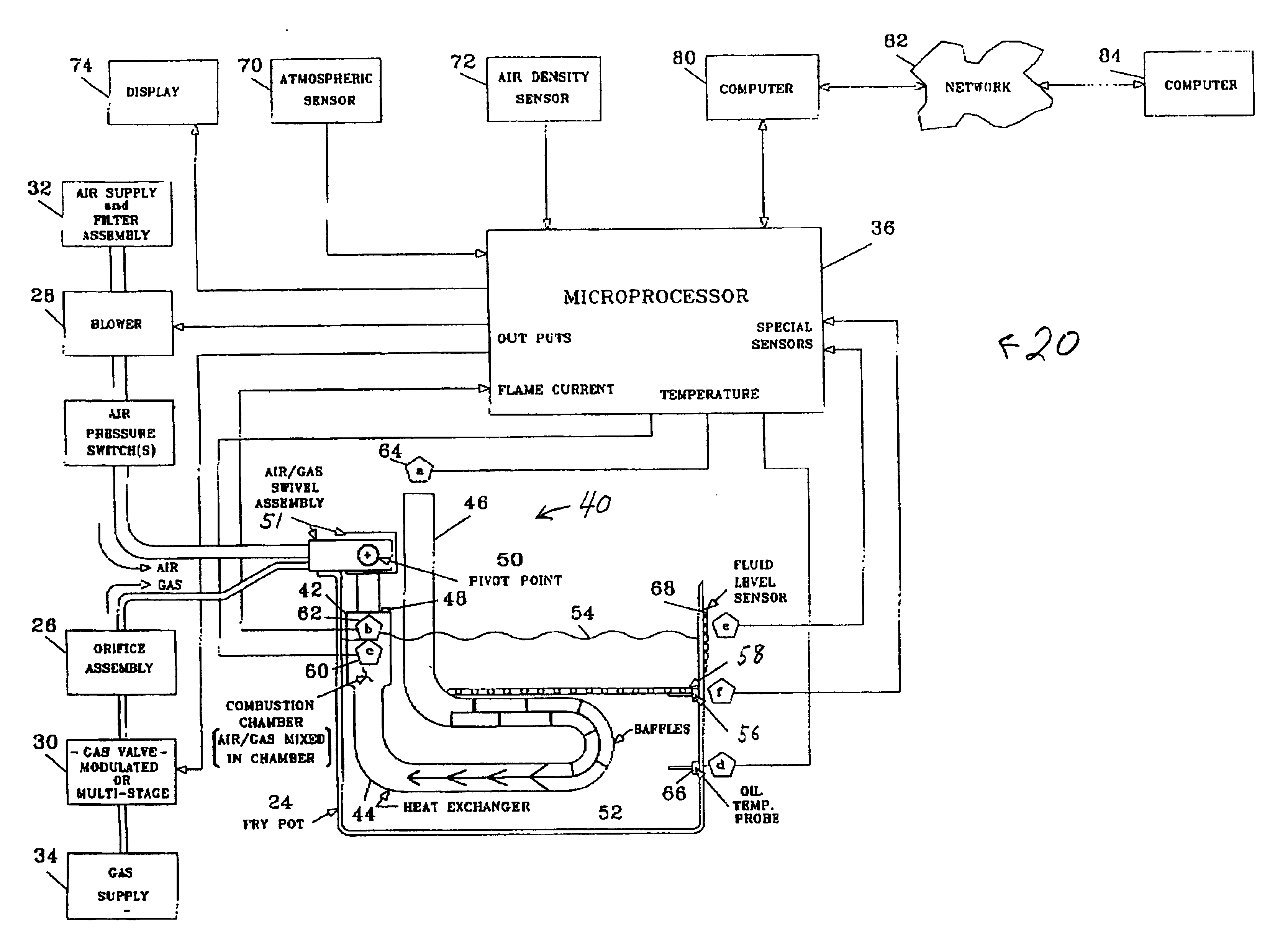
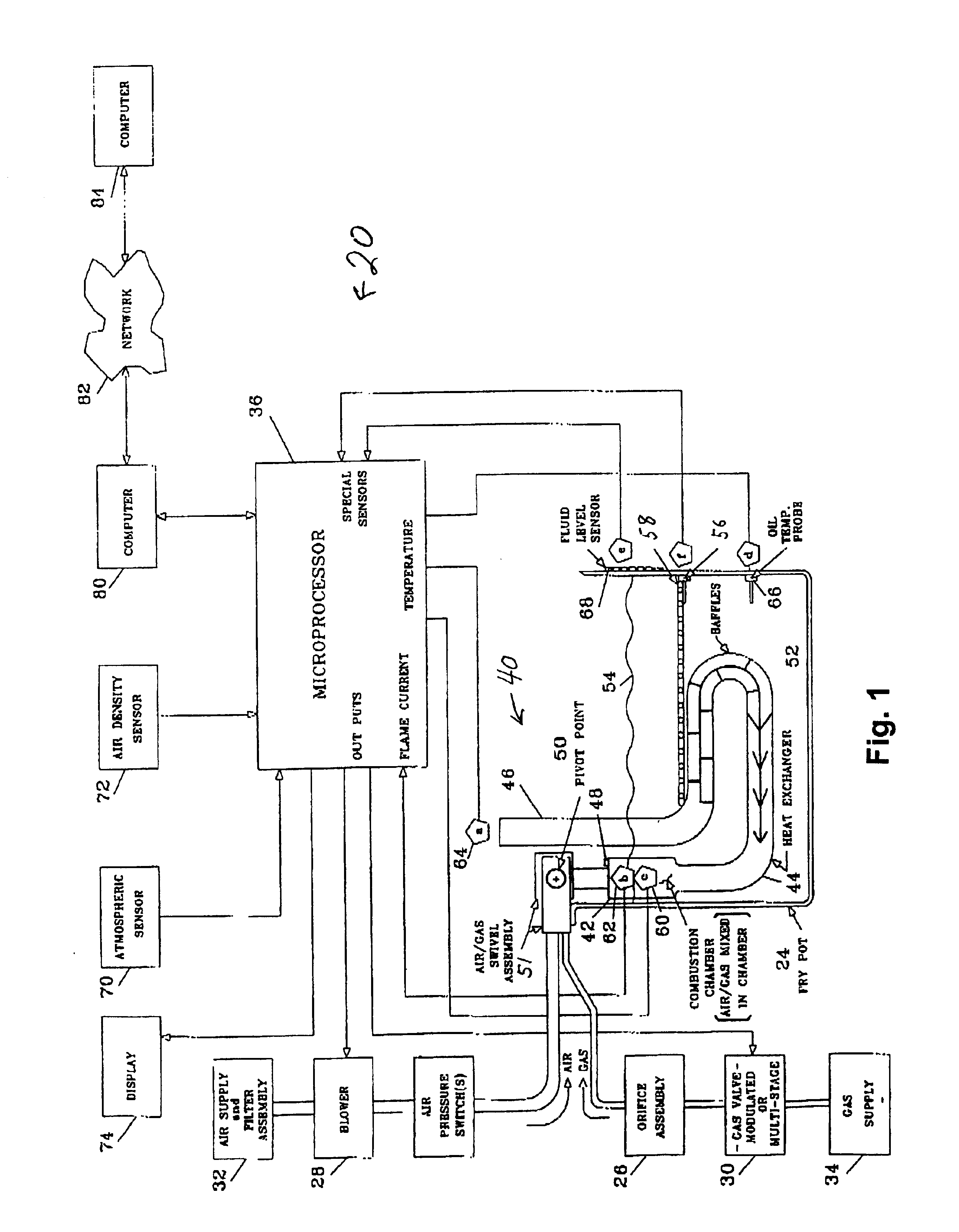
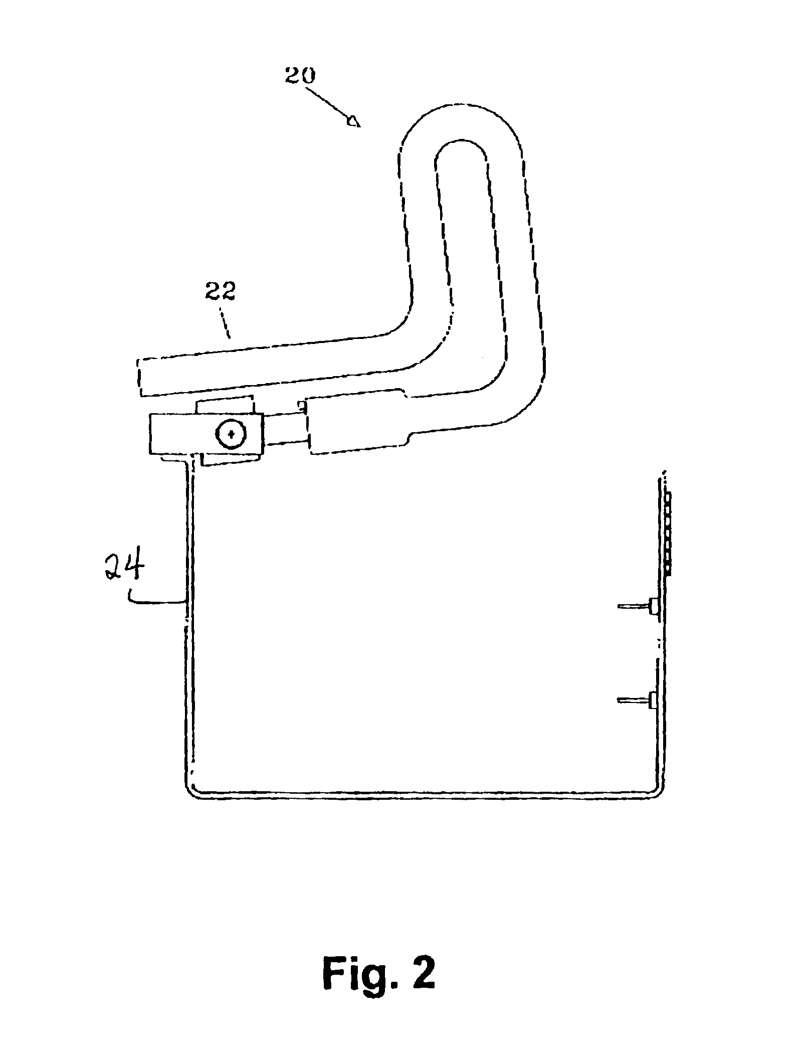
[0018]Referring to the FIG. 1, a frying apparatus 20 includes a fry pot 24, a gas orifice assembly 26, a blower 28, a gas valve 30, a control 36 and a combustion burner 40. Combustion burner 40 includes a combustion chamber 42, a heat exchanger 44, a flue 46 and an igniter 48. Gas orifice assembly 26 is connected to combustion chamber 42 to provide optimum gas flow that is injected therein.

[0019]Combustion chamber 42 includes an internal substantially cylindrical titanium liner within which the air / gas mixture is injected. Igniter 48 ignites or initiates combustion in combustion chamber 42. Heat exchanger 44 is connected to combustion chamber 42 so as to convey the combustion gas along its length and flue 46 to atmosphere. Heat exchanger 44 and flue 46 may be formed of one integral piece or of two or more parts that are connected together as a one-piece assembly. Contained within the heat exchanger is a baffle 29 comprised of fins progressively sized / formed to provide uniform heatin...


PUM


Abstract

Frying apparatus for frying food, such as French fries, vegetables, bakery goods, meat fish, poultry and the like, in a heated fluid contained in a fry pot. The fluid is heated by a combustion burner that has a heat exchanger removably disposed in the heating fluid. When removed from the fluid, the heat exchanger and the fry pot can be easily cleaned. The air and / or gas is injected into the combustion chamber so as to provide an air gas ratio that supports clean combustion. A control monitors various temperatures and other parameters at various locations of the frying apparatus to control the efficiency of the frying apparatus to approximate a predetermined efficiency by altering the air / gas ratio.

Description

[0001]This Application claims the benefit of U.S. Provisional Application No. 60 / 323,895, filed Sep. 21, 2001.FIELD OF THE INVENTION[0002]This invention relates to a frying apparatus with a removable heat exchanger. The present invention also relates to a frying apparatus and method for controlling the temperature of a cooking fluid thereof.BACKGROUND OF THE INVENTION[0003]Commercial gas fryers generally have a fry pot for containing a cooking fluid and a means for heating the cooking fluid. One type of fry pot, known as the open pot design, requires heat to be applied to the exterior sides of the fry pot. The open pot design has an advantage of being easily cleaned. Open pot designs use either an atmospheric burner or a forced combustion burner. Open pot designs with an atmospheric burner achieve an efficiency of about 45%, while open pot designs with forced combustion burners achieve an efficiency of about 65 to 70%. The disposition of the burner adjacent the exterior sides of the...

Claims


Application Information

Patent Timeline
IPC IPC(8): A47J37/12F23N1/02A23L5/10F23C5/02F23N5/00F23N5/02
CPCA47J37/1247A47J37/1266
Inventor TAYLOR, RAYMOND G.
Owner FRYMASTER CORPTHE
Learn More