Eureka AIR delivers breakthrough ideas for toughest innovation challenges, trusted by R&D personnel around the world.

Foldable furniture device

a furniture device and foldable technology, applied in the field of furniture devices, can solve the problem that users may easily injure their hands, and achieve the effect of convenient folding and unfolding

Inactive Publication Date: 2005-10-25
HABITEX
View PDF6 Cites 59 Cited by
  • Summary
  • Abstract
  • Description
  • Claims
  • Application Information

AI Technical Summary

Benefits of technology

[0006]Therefore, the object of the present invention is to provide a foldable furniture device that can be easily folded and unfolded.

Problems solved by technology

However, the user may easily injure his / her hand during the folding operation of the cross bars 86, 86′, i.e., the user's fingers may be pinched by the cross bars 86, 86′.

Method used


Image

  • Foldable furniture device
  • Foldable furniture device
  • Foldable furniture device

Examples


Embodiment Construction

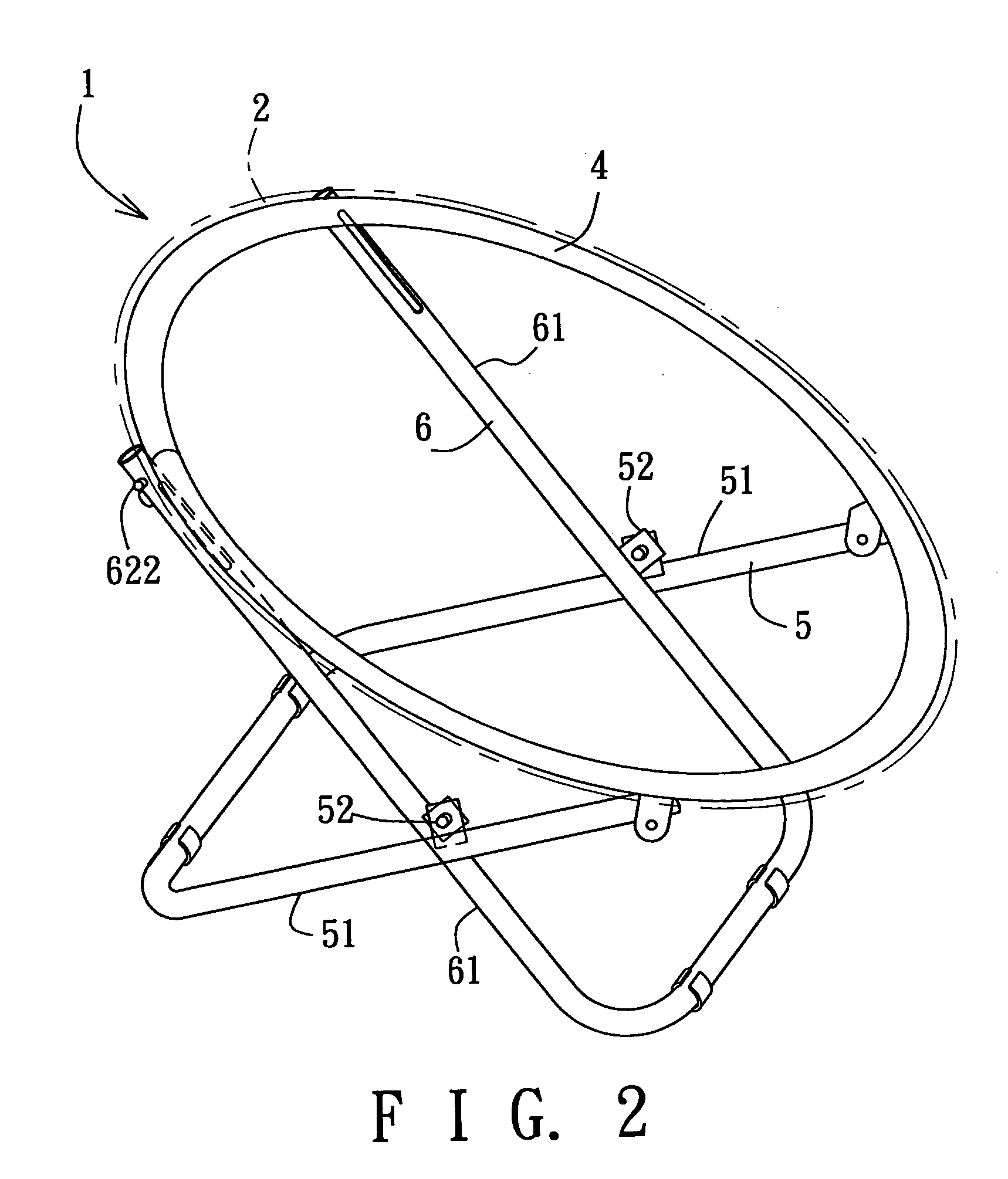
[0015]Referring to FIGS. 2 and 3, the preferred embodiment of a foldable furniture device according to the present invention is shown at “1” which designates a foldable chair. The chair 1 comprises a main frame 4, a first leg frame 5, a second leg frame 6, two slide rods 62, two securing units, and two locking units.

[0016]The main frame 4 is formed as a ring-shaped frame, and includes a pliable bag 2 that envelopes the ring-shaped frame.

[0017]The first leg frame 5 is substantially U-shaped, and includes two spaced-apart first leg sections 51 which have top ends connected pivotally to the main frame 4.

[0018]The second leg frame 6 is substantially U-shaped, and includes two spaced-apart second leg sections 61 which are connected pivotally and respectively to the first leg sections 51 through pivot members 52 so that the first and second leg frames 5, 6 are movable relative to each other between a folded state and an unfolded state.

[0019]Since the lengths of the first leg sections 51 a...


PUM


Abstract

A furniture device includes first and second leg frames pivotally connected to a main frame, and a slide rod inserted into and movable within the second leg frame. The second leg frame includes an elongate slot having first and second ends respectively proximate to and distal from the top end of the second leg frame. A securing unit has a fastening element extending through the slot and the slide rod and fixed to the main frame, and is operable to slide the fastening element to the first and second ends of the slot in unfolded and folded states of the furniture device, respectively. A locking unit is provided to lock the slide rod against movement when the fastening element moves to the first end of the slot.

Description

BACKGROUND OF THE INVENTION[0001]1. Field of the Invention[0002]The invention relates to a furniture device, more particularly to a foldable furniture device, such as a foldable chair.[0003]2. Description of the Related Art[0004]Referring to FIG. 1, a conventional foldable chair assembly 7 includes a leg frame 8 and a seat member 9. The leg frame 8 includes two intersecting U-shaped legs 81, each of which has front and rear leg sections 83, 84. The seat member 9 is connected between top ends of the front and rear leg sections 83, 84. The front leg sections 83 of the U-shaped legs 81 are connected pivotally to each other by a pivot member 85, and are interconnected by a cross bar 86. The rear leg sections 84 of the U-shaped legs 81 are connected pivotally to each other by another pivot member (not visible), and are interconnected by another cross bar 86′. Each of the cross bars 86, 86′ can be folded and unfolded. When unfolded, each cross bar 86, 86′ forms a straight line so as to po...

Claims


Application Information

Patent Timeline
Patent Type & Authority Patents(United States)
IPC IPC(8): A47C4/44A47C4/00A47C4/48
CPCA47C4/48
Inventor HSIEH, DUAN-CHENG
Owner HABITEX
Why Eureka
Eureka Blog
Learn More