
Electrical imaging in conductive and non-conductive mud

a technology of electrical imaging and conductive mud, which is applied in the field of well logging, can solve the problems of inaccuracy of borehole imaging, rapid wear of electrodes, and large hardware complexity, and achieve the effect of low resistivity

Active Publication Date: 2005-10-25
BAKER HUGHES INC
View PDF10 Cites 59 Cited by
  • Summary
  • Abstract
  • Description
  • Claims
  • Application Information

AI Technical Summary

Benefits of technology

The present invention is a method and apparatus for measuring the electrical properties of a formation surrounding a borehole with a measuring-while-drilling device. The apparatus includes a rotatable drill collar and at least one extendable stabilizer joined to the drill collar. The at least one transmitter injects an RF signal into the formation, and the at least one receiver measures the phase and attenuation of the RF signal upon propagation through the formation. The at least one receiver and the transmitter define a plurality of transmitter-receiver spacings. The invention allows for the determination of the electrical properties of the formation surrounding the borehole in real-time, which can aid in the evaluation of the quality of the drilling process and the stability of the formation.

Problems solved by technology

If the borehole wall is irregular, the contact and the current from the electrodes is irregular, resulting in inaccurate imaging of the borehole.
The addition of a mixer and the secondary oscillator, adds greatly to the complexity of the hardware.
In a MWD tool, this results in rapid wearing away of the electrodes, necessitating frequent replacement.

Method used


Image

  • Electrical imaging in conductive and non-conductive mud
  • Electrical imaging in conductive and non-conductive mud
  • Electrical imaging in conductive and non-conductive mud

Examples


Embodiment Construction

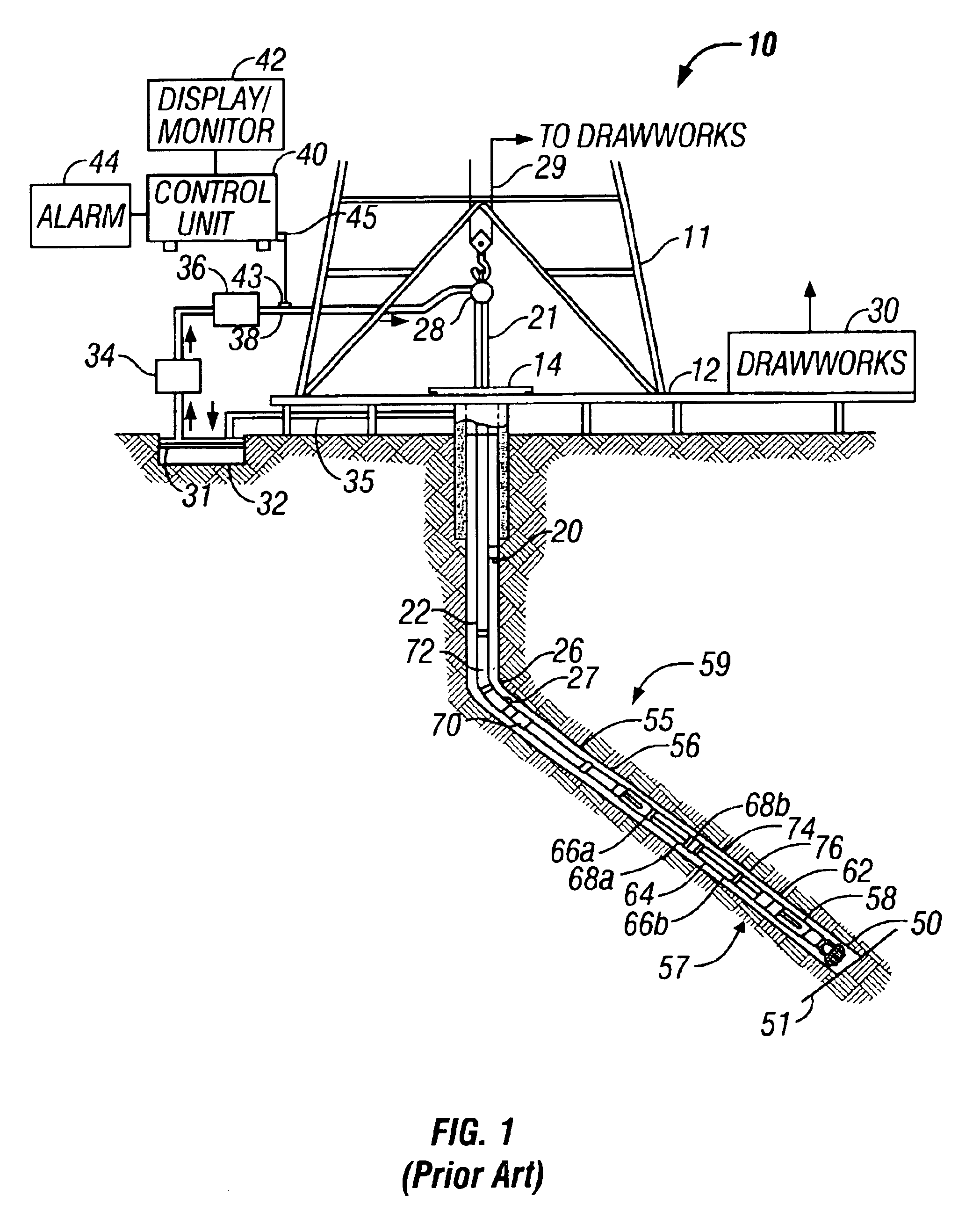
[0027]FIG. 1 shows a schematic diagram of a drilling system 10 having a downhole assembly containing an acoustic sensor system and the surface devices according to one embodiment of present invention. As shown, the system 10 includes a conventional derrick 11 erected on a derrick floor 12 which supports a rotary table 14 that is rotated by a prime mover (not shown) at a desired rotational speed. A drill string 20 that includes a drill pipe section 22 extends downward from the rotary table 14 into a borehole 26. A drill bit 50 attached to the drill string downhole end disintegrates the geological formations when it is rotated. The drill string 20 is coupled to a drawworks 30 via a kelly joint 21, swivel 28 and line 29 through a system of pulleys 27. During the drilling operations, the drawworks 30 is operated to control the weight on bit and the rate of penetration of the drill string 20 into the borehole 26. The operation of the drawworks is well known in the art and is thus not des...


PUM


Abstract

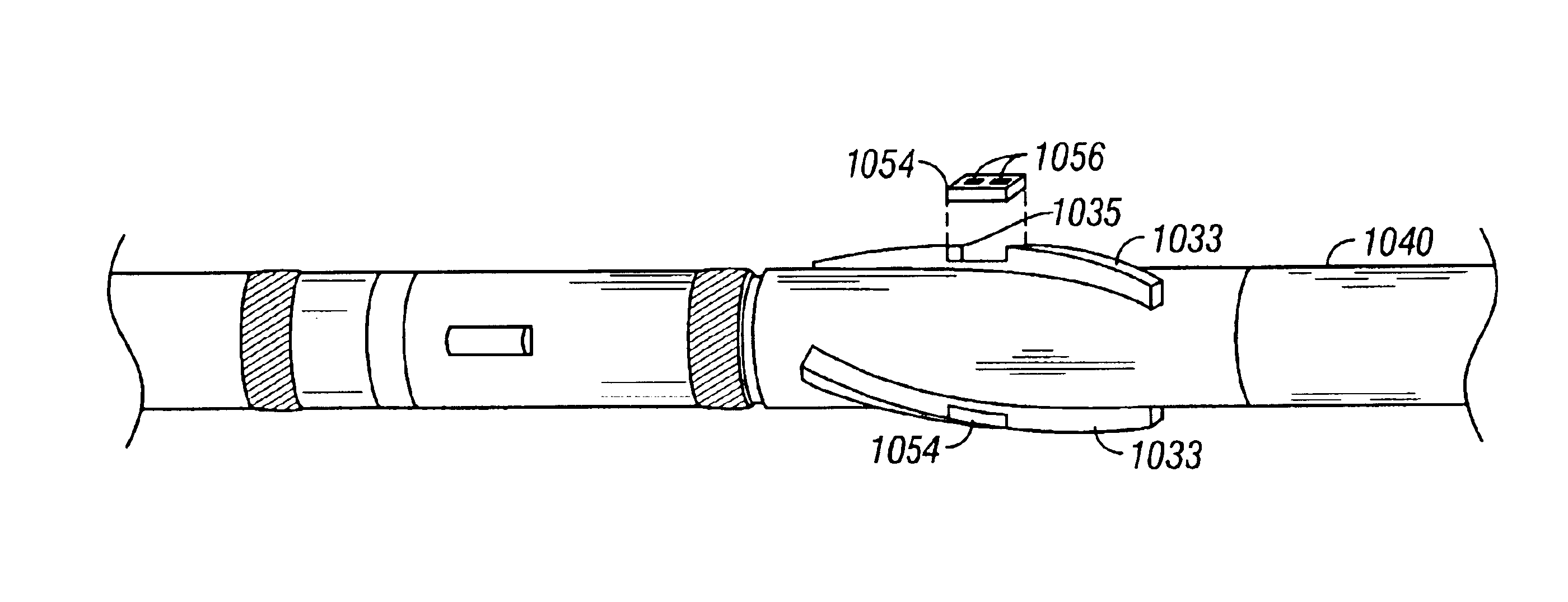
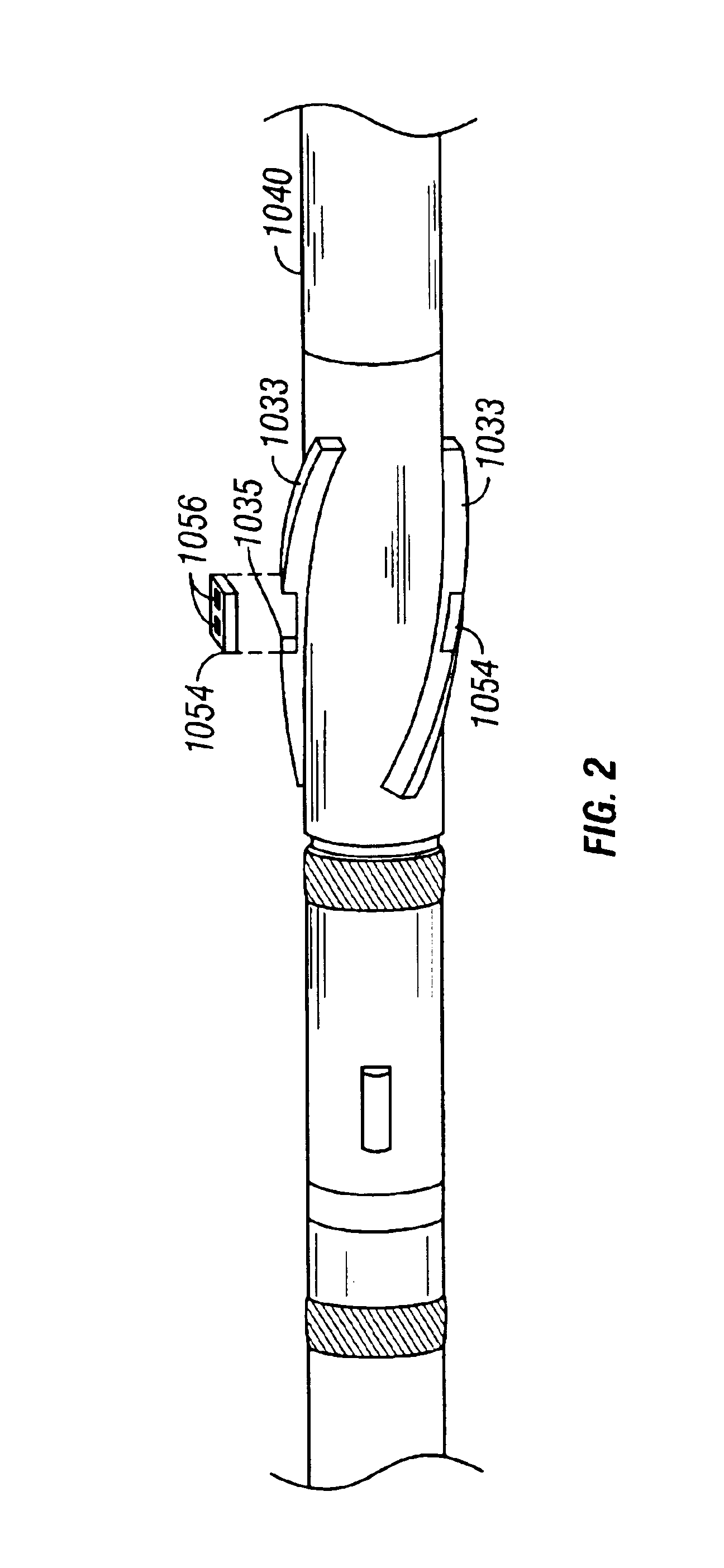
The invention is a method and apparatus for determining an electrical property a formation surrounding a borehole with a measuring-while-drilling device. The apparatus an antenna configuration disposed along the outer face of an extendable stabilizer joined to a rotatable drill collar. Typically, two receivers and two transmitters are spaced along the longitudinal axis of the drill collar, with the two receivers spaced symmetrically in between the two transmitters. Alternatively, receivers and transmitters can be spaced along the circumference, possibly over multiple stabilizers. Multiple assemblies can be used. Data can be obtained with the transmitter-receiver assembly held in a stationary position or rotating circumferentially. Apparatus can be operated in a “broadside” configuration, an “endfire” configuration, or a configuration in which transmitter coils and receiver coils are oriented orthogonally to each other.

Description

BACKGROUND OF THE INVENTION[0001]1. Field of the Invention[0002]The present invention relates to well logging. In particular, the present invention is an apparatus and method for imaging of subsurface formations using electrical methods.[0003]2. Description of the Related Art[0004]U.S. Pat. No. 4,468,623, issued to Gianzero, discloses tool mounted pads, each with a plurality of small measure electrodes from which individually measurable survey currents are injected toward the wall of the borehole. The measure electrodes are arranged in an array in which the measure electrodes are so placed at intervals along at least a circumferential direction (about the borehole axis) as to inject survey currents into the borehole wall segments which overlap with each other to a predetermined extent as the tool is moved along the borehole. The measure electrodes are made small to enable a detailed electrical investigation over a circumferentially contiguous segment of the borehole so as to obtain ...

Claims


Application Information

Patent Timeline
Patent Type & Authority Patents(United States)
IPC IPC(8): E21B17/00E21B17/10E21B47/01E21B47/00G01V3/30G01V3/18
CPCE21B17/1078E21B47/0002E21B47/01G01V3/30E21B47/002E21B47/0025E21B17/10
Inventor CHEMALI, ROLAND E.FOLBERTH, MARTINWANG, TSILIRITTER, RENE
Owner BAKER HUGHES INC
Learn More