
Device for non-contact transmission of electrical signals and/or energy

a non-contact, electrical signal technology, applied in the direction of post-communication radio transmission, transmission, inductance, etc., can solve the problems of not being able to operate at operating frequencies in the mhz range and above, not being able to transmit signals with a bandwidth, and not being able to meet the needs of wide-band electrical signal transmission, etc., to achieve simple matching and low-cost structure

Inactive Publication Date: 2005-10-18
SCHLEIFRING & APPBAU
View PDF1 Cites 50 Cited by
  • Summary
  • Abstract
  • Description
  • Claims
  • Application Information

AI Technical Summary

Benefits of technology

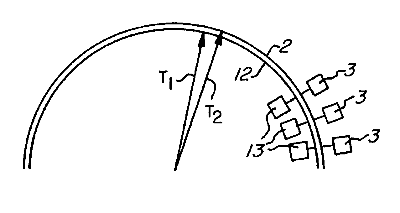
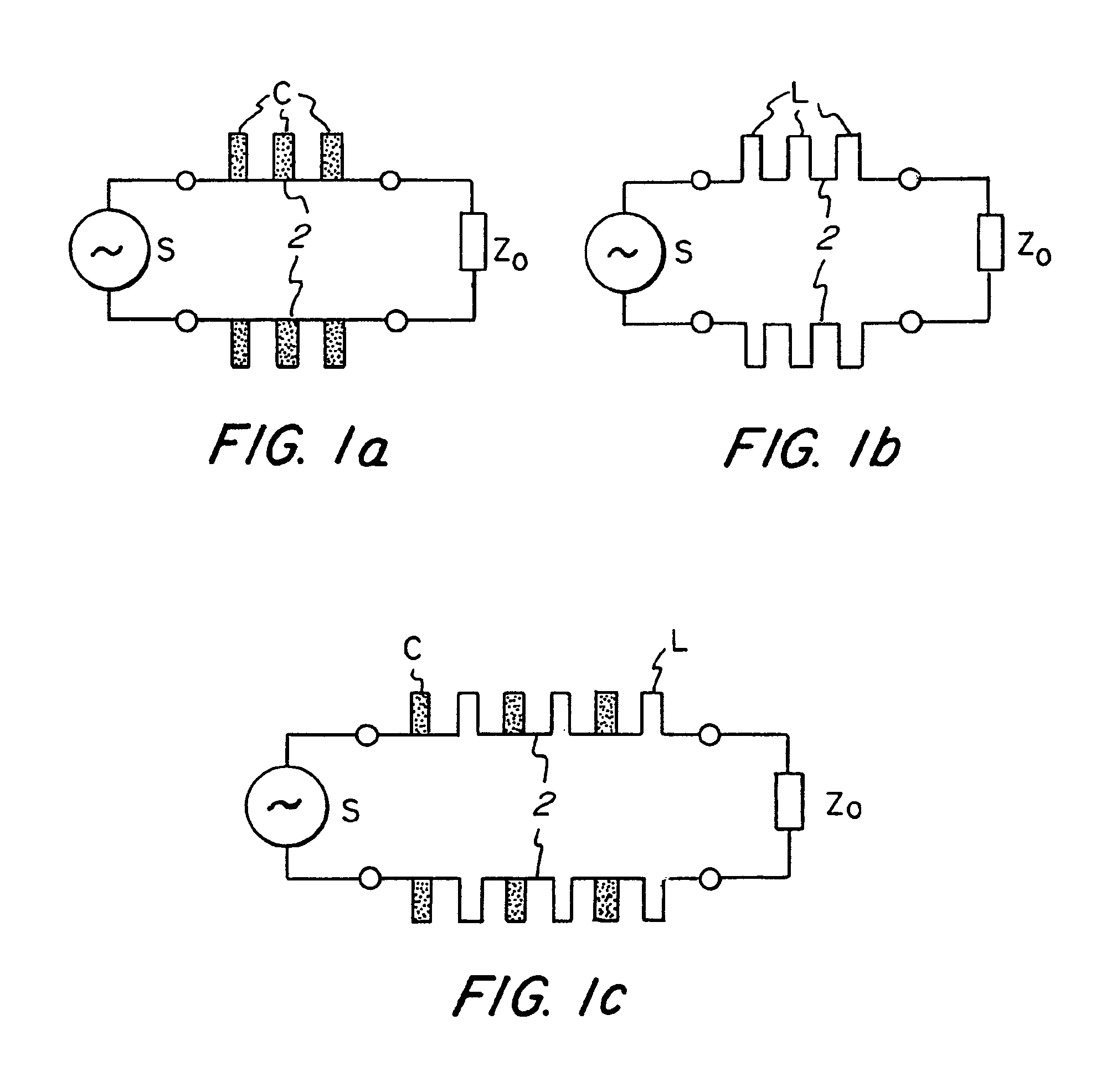
[0024]In the inventive approach defined in claim 1 each of the coupler elements, which are provided on at least one part, contains at least one resonator which consists of a single element able to resonate per se and independently of the other coupler elements. The resonant frequency of the resonator or resonators, respectively, is approximately equal to the frequency of the signals to be transmitted. The individual resonators are interconnected via a line which is terminated in a reflection-free manner. It is thus possible to transmit the signals or the electrical energy to be transmitted, respectively, with a high efficiency at comparatively low losses due to emission. At the same time, the structure of the inventive device is a simple and hence low-cost design. The resonance of the individual resonators may be a serial or parallel resonance.
[0064]It is moreover possible that the coupler elements are shielded by a shield of electrically conductive material. This shield may comprise the coupler elements with or even without the line system or parts thereof. The shield produces its best effect when it encompasses the coupler elements as far as possible.

Problems solved by technology

Even though that known device is very well suited for transmitting electrical energy, it is not appropriate for the wide-band transmission of electrical signals due to the fact that it operates as Resonanzübertrager.
Moreover, as a result of the three-dimensional arrangement of the coils, it cannot be employed at operating frequencies in the MHz range and above.
That device, which originates from the year 1983, entails, however, also the disadvantage that it is not suitable for transmitting signals with a bandwidth which is required at present for computer tomographs, because reflections occur already at low frequencies on the coupler elements.
Even though the use of separate amplifiers for each coupler element would be a remedy the use of a great number of amplifiers would result in very high costs.
Furthermore the structure via the open coupler elements results in a very high electromagnetic noise radiation.
On the other hand, the structure of the rotating coupler is complex and hence expensive, particularly when the system should have a wide diameter, e.g. of the size required in computer tomographs.
The disadvantage of such strip lines is the wide-band emission of high-frequency energy from the line serving as a coupler:
Another disadvantage of these known methods and devices consists in the aspect that in the event that signals are coupled into the line by the units adapted for relative movement, only a little amount of energy can be transmitted.
But this results in a low line impedance and hence in an increased sensitivity to noise.

Method used


Image

  • Device for non-contact transmission of electrical signals and/or energy
  • Device for non-contact transmission of electrical signals and/or energy
  • Device for non-contact transmission of electrical signals and/or energy

Examples


Embodiment Construction

[0082]In the following figures the same reference numerals have been used to denote identical elements or elements producing the same effects so that partly a repeated discussion may be omitted here.

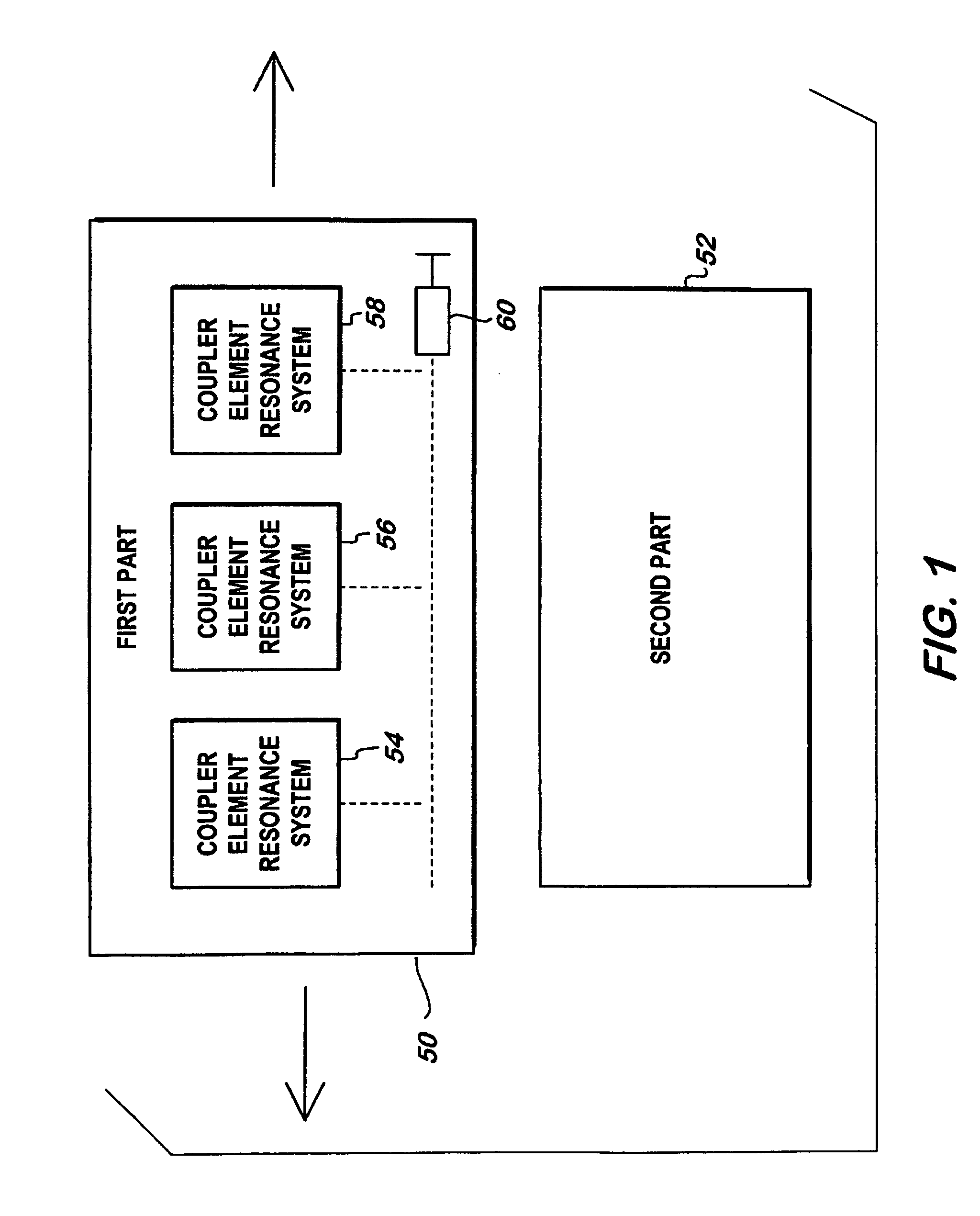
[0083]FIG. 1 illustrates an advantageous embodiment of the present invention including first part 50 and second part 52. First part 50 includes a plurality of coupler elements 54, 56, 58. Coupler elements 54, 56, 58 comprise a conductor structure configured as a cascade circuit, which is provided with a termination 60 to minimize signal reflection. Each coupler element illustrated on first Part 50 is configured as a resonance system independent of each of the other coupler elements on first part 50, which has a resonance frequency higher than the highest frequency of the wide-band signals to be terminated. It should be noted that while coupler elements 54, 56, 58 are shown in first part 50, they may alternatively be located in second part 52. It is only necessary that they are provided o...


PUM


Abstract

A device for non-contact transmission of electrical signals or energy between two parts mobile relative to each other comprising electromagnetic near-field coupler elements on the two parts, wherein the coupler elements on at least one part form a cascade circuit terminated in a manner substantially free from reflection, and each coupler element is an independent resonance system having a resonance frequency higher than a highest frequency of wide-band signals to be transmitted. An alternatively structured device in which each coupler element on one part includes an element that resonates independently and has a resonance frequency approximately equal to the frequency of signals or energy to be transmitted including developments in which the coupler elements operate on differential signals, or analyzer means determine the spacing between the two parts, or at least one part comprises symmetrical lines for supplying differential energy signals to two coupler elements.

Description

[0001]This applicaiton claims the benefit of the filing date of PCT / DE98 / 00512 filed Jan. 5, 1998, which claims the benefit of the filing date of German Applicantion Nos. 197 00 110.6 filed Jan. 3, 1997 and 197 01 357.0 filed Jan. 16, 1997.FIELD OF THE INVENTION[0002]The present invention relates to device for non-contact transmission of electrical signals and / or energy between at least two parts mobile relative to each other, wherein a plurality of defined electromagnetic coupler elements is provided on at least one part, which have a near field inducing the non-contact transmission.[0003]Such devices are used for the transmission of electrical signals or electrical energy, respectively, between two or more parts mobile relative to each other. This movement may be a rotating, a translational or a combined movement.[0004]For the sake of easy understanding a distinction is not made in the present description between the transmission among mutually mobile units and a stationary unit a...

Claims


Application Information

Patent Timeline
IPC IPC(8): H01F38/14H01P1/06H04B5/00H04B7/26H01P7/08H02J17/00H04B5/02
CPCH01F38/14H01P1/06H01P1/067H04B5/00H04B5/0012H01F2038/146H04B5/0031H04B5/0037H04B5/22H04B5/72H04B5/79
Inventor LOHR, GEORG
Owner SCHLEIFRING & APPBAU
Learn More