
Multiplex electrical receptacle

a multi-functional, electrical receptacle technology, applied in the direction of coupling device connection, coupling base/case, tumbler/rocker switch details, etc., can solve the problems of not disclosing or suggesting, wiring errors, and increasing installation time and cost, so as to reduce labor and materials.

Inactive Publication Date: 2005-10-18
PYRROS CHRESTOS T
View PDF7 Cites 55 Cited by
  • Summary
  • Abstract
  • Description
  • Claims
  • Application Information

AI Technical Summary

Benefits of technology

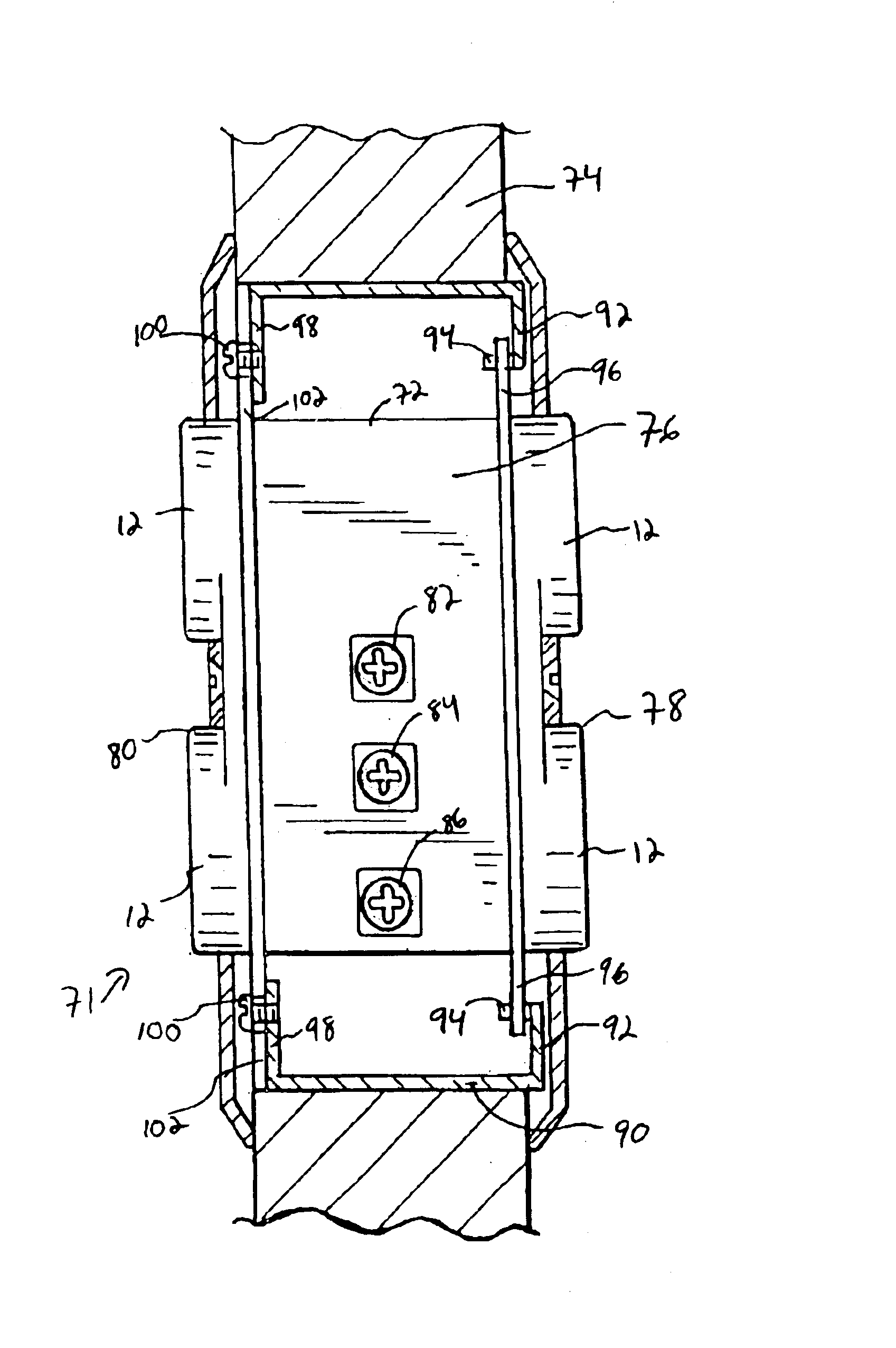
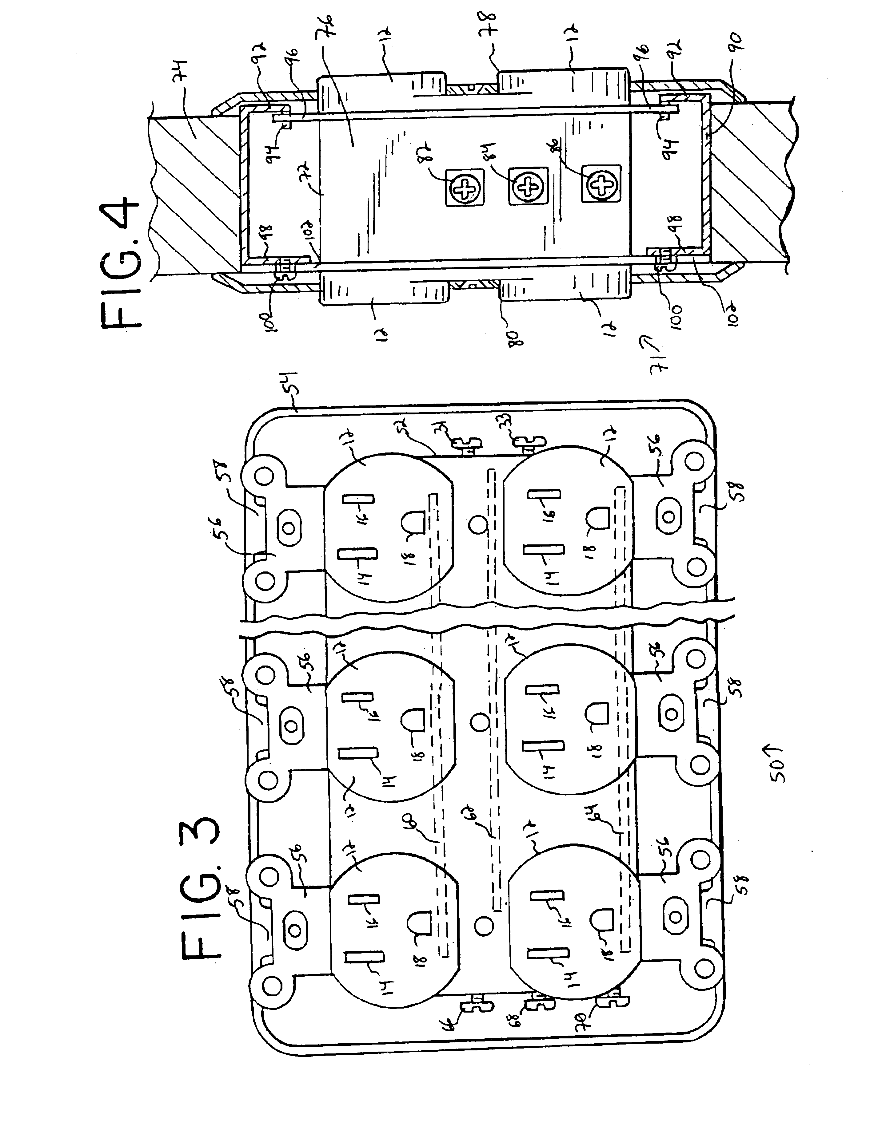
"The present invention provides a multiplex receptacle that can be mounted in a wall and connected to a single power source. The receptacle has multiple outlets that can be positioned on both sides of the wall, allowing for flexibility in placement. The receptacle can also have additional outlets on both sides. The internal circuitry of the receptacle allows for the connection of each outlet to the power source with a single electrical cable. The receptacle outlets have standard apertures for connection to a three-pronged plug. The receptacle can be expanded to include additional outlets on each side of the wall. The receptacle outlets can be side by side or positioned above each other, depending on the needs of the room. The receptacle is secured to the electrical junction box using mounting brackets. The invention also provides an electrical box for mounting receptacle outlets on both sides of a wall separating two rooms."

Problems solved by technology

This can lead to mistakes in wiring and increases the time and cost of installation.
Bagga does not disclose or suggest providing a housing with flanges for placement of the receptacle in a standard in-wall outlet box, or expanding the receptacle to provide more than four receptacle outlets or placing receptacle outlets on more than one side of the housing.

Method used


Image

  • Multiplex electrical receptacle
  • Multiplex electrical receptacle
  • Multiplex electrical receptacle

Examples


Embodiment Construction

[0056]While this invention is susceptible of embodiments in many different forms, there is shown in the drawings and will herein be described in detail preferred embodiments of the invention with the understanding that the present disclosure is to be considered as an exemplification of the principles of the invention and is not intended to limit the broad aspects of the invention to the embodiments illustrated.

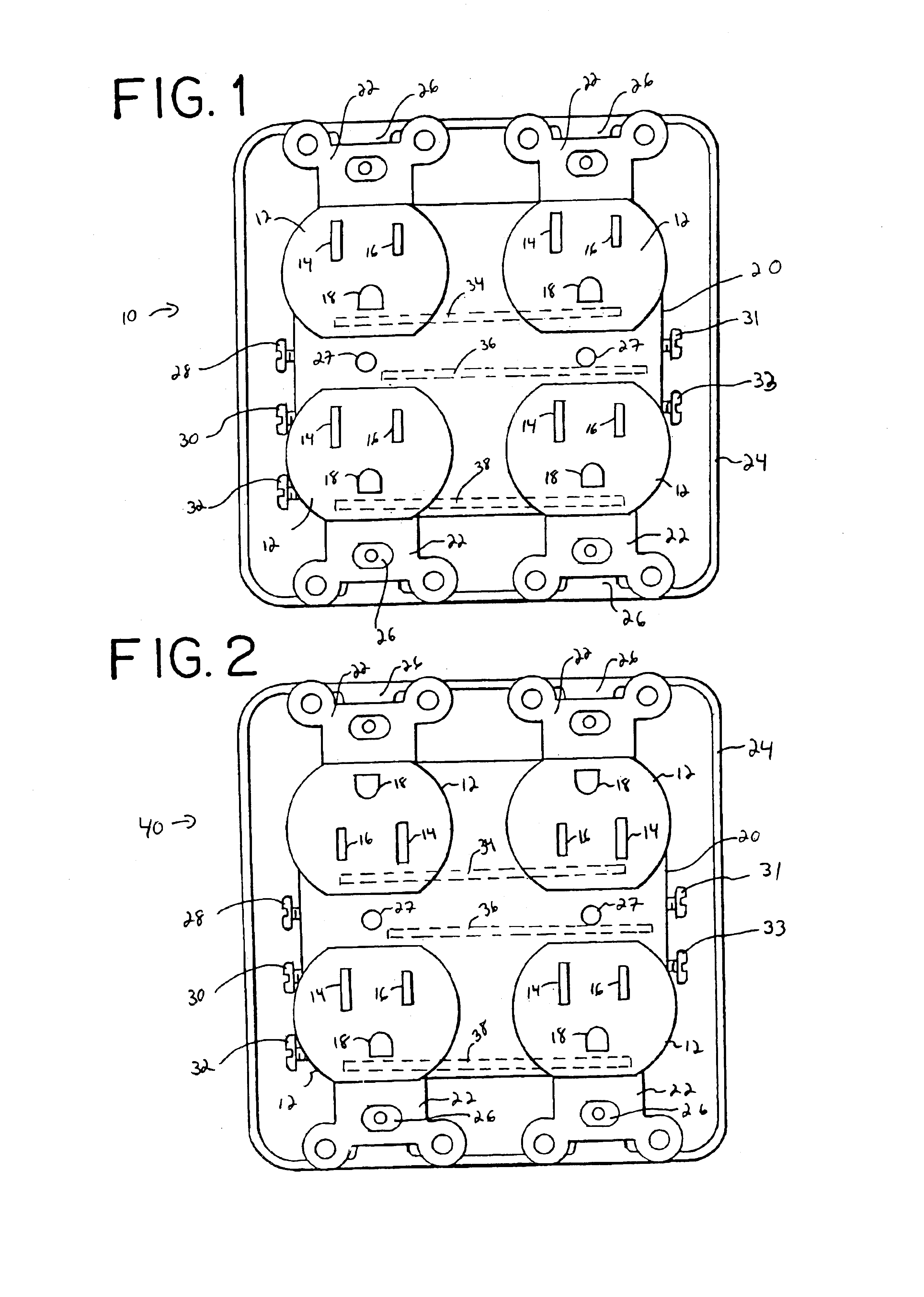
[0057]Referring to FIG. 1, one embodiment of a multiplex receptacle 10 of the present invention is shown having four receptacles or electrical outlets 12 (i.e., a quadplex receptacle). Each of the four outlets 12 include three apertures for receiving a conventional three-pronged plug. Specifically, each outlet 12 includes a first blade slot 14 to receive the neutral prong or blade of the plug, a second blade slot 16 to receive the hot blade of the plug, and a ground slot 18 to receive a ground prong of the plug.

[0058]The four electrical outlets 12 are collectively contained in...


PUM


Abstract

A multiplex electrical outlet receptacle comprises a housing containing four or more receptacle outlets. The housing contains at least one tab extending from the top of the housing and at least one tab extending from the bottom of the housing to permanently secure the housing to an in-wall electrical box. A single electrical cable connection on the housing connects each of the four or more electrical receptacle outlets to a power source. The housing of the multiplex electrical outlet receptacle includes internal wiring and / or buses to connect each of the outlets in common to the electrical cable. Additionally, a two-sided multiplex receptacle and a corresponding electrical box are configured to provide electrical outlets to both sides of a wall. Additionally, a multi-receptacle plug-in adapter configured to allow more than one transformer type plug to connect to the adapter at the same time. Further, a multi-switch device comprises two or more switches commonly wired to a source of electrical power in a single housing. The switches control distinct loads. Additionally, the switches can be on opposing sides of the housing for providing switches to both sides of a wall.

Description

TECHNICAL FIELD[0001]The present invention is generally related to an electrical receptacle having a plurality of receptacle outlets wired in common to a single source of electrical energy, and more particularly, to a standard wall mounted electrical receptacle having four, six, eight or more receptacle outlets wired in common to a single cable. The present invention is also generally related to a two-sided electrical receptacle and an electrical box configured to house the two-sided electrical receptacle, and more particularly, to a two-sided electrical receptacle having electrical outlets on both sides for placement in a wall common to two adjacent rooms and to an electrical box having an opening for each side of the electrical receptacle and sized to span the width of the wall.[0002]The present invention is also generally related to an improved electrical receptacle adapter, and more particularly, to an electrical plug in adapter having multiple adapter outlets configured to rece...

Claims


Application Information

Patent Timeline
Patent Type & Authority Patents(United States)
IPC IPC(8): H01R25/00H01R31/06
CPCH01R25/006H01R31/06
Inventor PYRROS, CHRESTOS T.
Owner PYRROS CHRESTOS T
Learn More