
Data transfer apparatus and method

a data transfer and data technology, applied in the field of data transfer apparatus and method, can solve the problems of increasing the size, increasing deteriorating system performance, and achieve the effects of reducing the amount of hardware, reducing the amount of information to be transferred, and reducing the use of bus

Inactive Publication Date: 2005-10-11
FUJITSU LTD
View PDF9 Cites 27 Cited by
  • Summary
  • Abstract
  • Description
  • Claims
  • Application Information

AI Technical Summary

Benefits of technology

[0018]The present invention has been devised in view of the above problems, and an object of the invention is to provide a data transfer apparatus and method that can make efficient use of the memory and the common bus and can achieve increased communication processing speed.
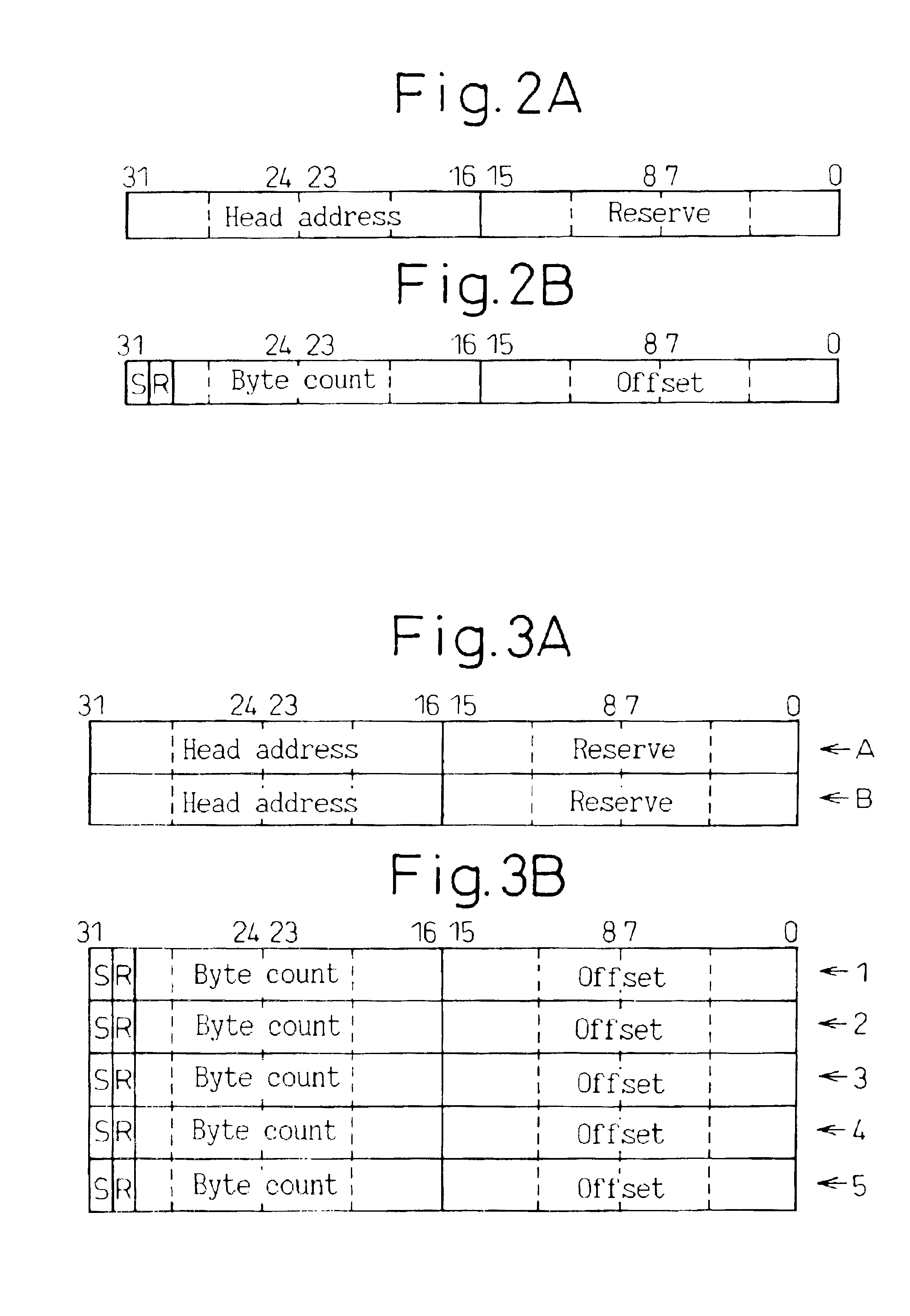
[0029]With the above-described configuration, the necessary storage area, and hence the amount of hardware, can be reduced by separating the descriptor information into common information and individual information and storing them separately. Furthermore, as the descriptor common information need not be transferred each time a data transfer occurs, the amount of information to be transferred can be reduced, and bus usage thus decreases. As a result, the bus can be used for other processing operations, which serves to improve system performance.
[0030]Further, in the configuration supporting a descriptor chain, a chain bit indicating the presence or absence of a descriptor chain is provided in the descriptor information, and the storage mechanism for storing the descriptor information is constructed in a FIFO structure with provisions made to automatically select the next descriptor in the FIFO when the chain bit is ON; this configuration eliminates the need for the next descriptor address and serves to reduce the amount of information to be carried in the descriptor, and hence the size of the storage mechanism for storing the descriptor information can be reduced, achieving a reduction in the amount of hardware. Furthermore, as there is no need to transfer the next descriptor address, bus usage decreases, increasing the availability of the common bus for other processing operations, and system performance can thus be improved.

Problems solved by technology

Here, when the descriptor information is stored in its entirety in the descriptor storage mechanism as described above, if the storage areas, etc. for DMA control are large in size or in number, the amount of information carried in the descriptor becomes large, necessitating a corresponding increase in the size of the storage mechanism for storing the descriptor information, and hence resulting in an increase in the amount of hardware.
Furthermore, when the amount of information carried in the descriptor becomes large, as the number of transfers of the descriptor information increases, the number of times the common bus is used increases, making the common bus unavailable for other processing operations; this can result in a degradation of system performance.
Furthermore, when the next descriptor address is added, the number of transfers of the descriptor information increases, increasing the number of times the common bus is used and thus making the common bus unavailable for other processing operations; this can result in a further degradation of system performance.

Method used


Image

  • Data transfer apparatus and method
  • Data transfer apparatus and method
  • Data transfer apparatus and method

Examples


embodiment 1

[0058

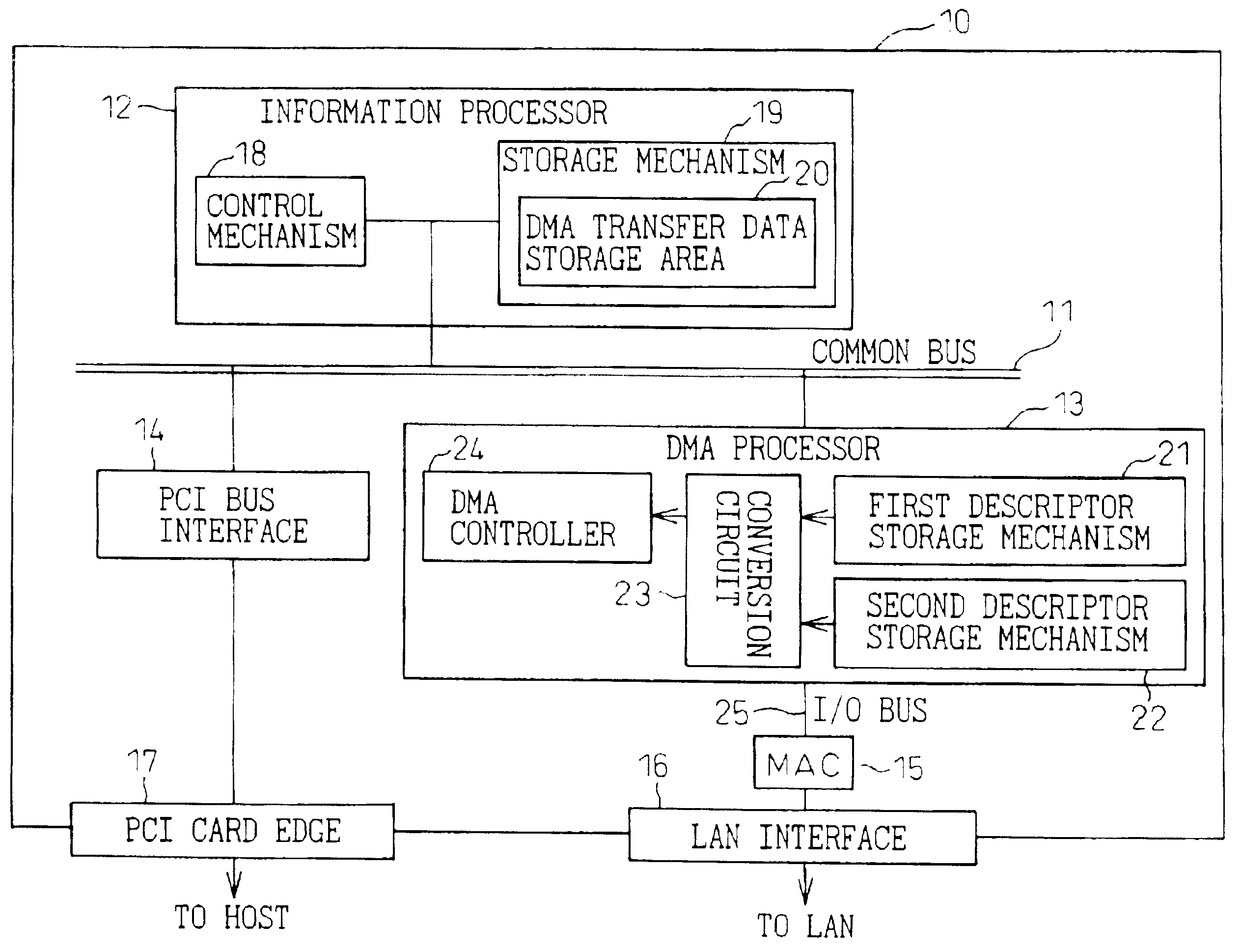
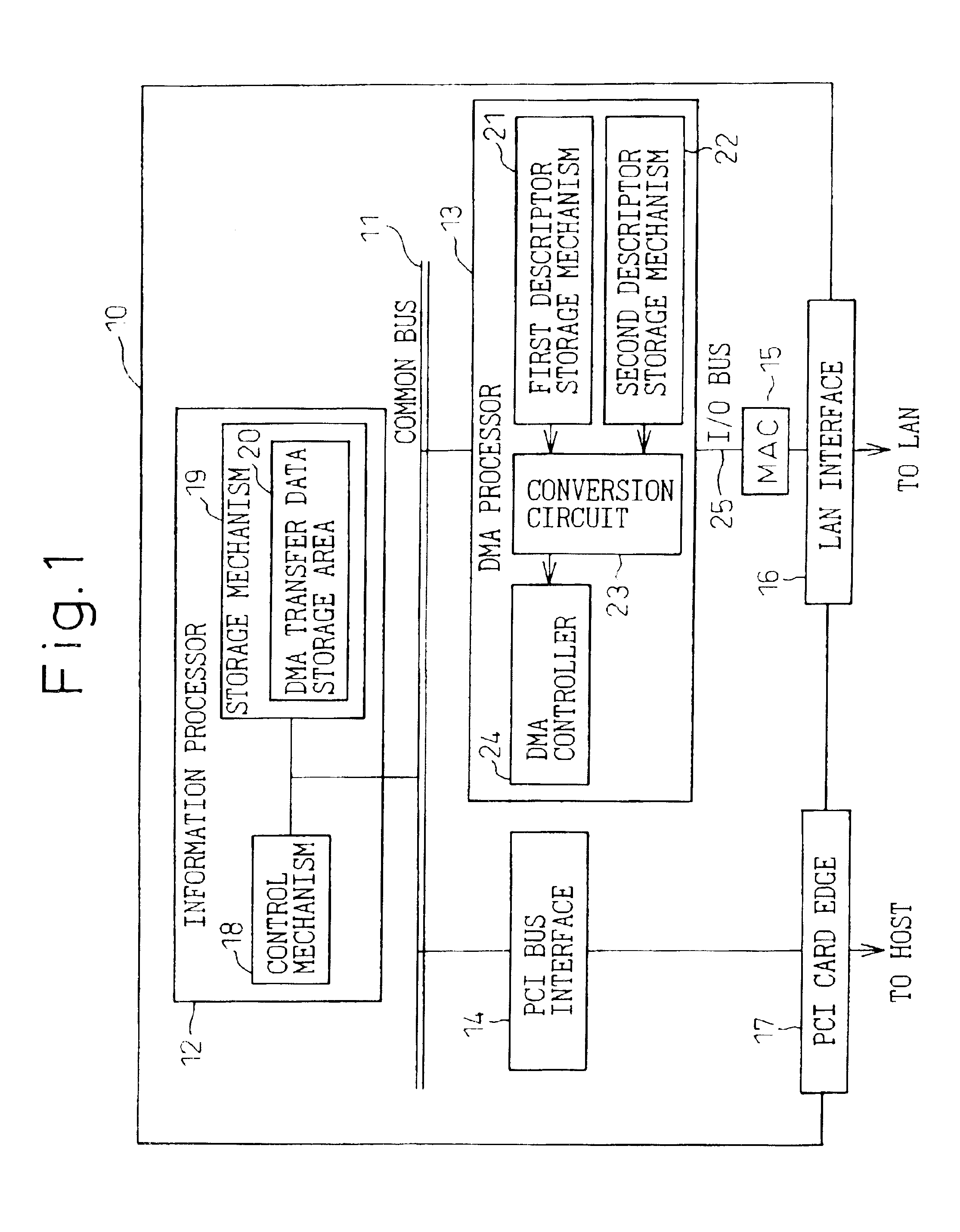
[0059]FIG. 1 is a block diagram showing the functional configuration of one embodiment of a LAN card to which the present invention is applied. The LAN card is a communication control processing device which supports a connection to a LAN (Local Area Network). As shown, the LAN card proper 10 comprises an information processor 12, a DMA (Direct Memory Access) processor 13, and a PCI bus (Peripheral Component Interconnect Bus) interface 14 interconnected via a common bus 11.

[0060]The information processor 12 includes a control mechanism 18 and a storage mechanism 19. The storage mechanism 19 is a device (memory) for storing software, data, etc. and includes a DMA transfer data storage area 20. The control mechanism 18 is a device (CPU) for executing software instructions, and accomplishes the task of writing descriptor information to a first descriptor storage mechanism 21 and a second descriptor storage mechanism 22 within the DMA processor 13 and the task of writing DMA transf...

embodiment 2

[0092

[0093]FIG. 11 is a block diagram showing the functional configuration of another embodiment of a LAN card to which the present invention is applied. The LAN card proper 10 shown here comprises an information processor 12, a DMA (Direct Memory Access) processor 13, and a PCI bus (Peripheral Component Interconnect Bus) interface 14 interconnected via a common bus 11.

[0094]The information processor 12 includes a control mechanism 18 and a storage mechanism 19. The storage mechanism 19 is a device (memory) for storing software, data, etc. and includes a DMA transfer data storage area 20, a first descriptor storage mechanism 21, and a second descriptor storage mechanism 22. The control mechanism 18 is a device (CPU) for executing software instructions, and accomplishes the task of writing descriptor information to the first descriptor storage mechanism 21 and the second descriptor storage mechanism 22 within the storage mechanism 19 and the task of writing DMA transfer data to the D...

embodiment 3

[0110

[0111]Lastly, a third embodiment of a LAN card according to the present invention will be described. The basic configuration of the third embodiment is the same as that of the first embodiment shown in FIG. 1, except that modifications are made to the first embodiment to support a descriptor chain.

[0112]FIGS. 15A and 15B are format diagrams showing the formats of the descriptor common information and descriptor individual information, respectively, according to the present embodiment. As can be seen from a comparison with FIGS. 2A and 2B relating to the earlier described first embodiment, the descriptor common information (FIG. 15A) in the present embodiment is the same as that (FIG. 2A) in the first embodiment.

[0113]On the other hand, the descriptor individual information (FIG. 15B) in the present embodiment somewhat differs from that (FIG. 2B) in the first embodiment, in that bit 30 is used as a chain bit (C). This chain bit (C) is a bit that indicates whether a plurality of ...


PUM


Abstract

A data transfer apparatus and method that can make efficient use of a memory and a common bus by controlling a DMA controller through descriptor control, and can thereby achieve a data transfer with increased communication processing speed. The data transfer apparatus, which executes a DMA transfer by controlling the DMA controller through the use of a descriptor, includes: a first storage mechanism for storing descriptor common information that can be shared among a plurality of descriptors; a second storage mechanism for storing descriptor individual information that differs for each individual descriptor; and a conversion circuit for taking as inputs the descriptor common information read out of the first storage mechanism and the descriptor individual information read out of the second storage mechanism, and for outputting descriptor information to be supplied to the DMA controller.

Description

BACKGROUND OF THE INVENTION[0001]1. Field of the Invention[0002]The present invention relates to a data transfer apparatus and method, and more particularly to a data transfer apparatus having a DMA (Direct Memory Access) controller, and a method for the same.[0003]2. Description of the Related Art[0004]In small computers, DMA transfer is employed which transfers data directly between an I / O device and a memory or between memories without the intervention of the CPU, and a DMA controller is used for such DMA transfer. Loaded with a memory address, transfer size, and other values, the DMA controller is activated to execute a DMA transfer.[0005]In recent years, a method for controlling the DMA controller through descriptor control has been proposed in order to prevent system efficiency degradation which can occur when the host system controls data transfers in real time (refer, for example, to Japanese Unexamined Patent Publication No. 5-204829).[0006]FIG. 20 is a format diagram showi...

Claims


Application Information

Patent Timeline
Patent Type & Authority Patents(United States)
IPC IPC(8): G06F13/20G06F13/28
CPCG06F13/28
Inventor YOSIMOTO, ATUYUKIHAYASAKA, KAZUMISAITO, HIROSHISUETSUGU, YOSHIMASA
Owner FUJITSU LTD
Learn More