
Paint mixer with damping frame

a paint mixer and damping frame technology, applied in the field of paint mixing, can solve problems such as significant imbalance and inability to adjust the damping effect, and achieve the effect of reducing vibration and reducing the effect of vibration

Inactive Publication Date: 2005-10-11
RED DEVIL EQUIP
View PDF30 Cites 25 Cited by
  • Summary
  • Abstract
  • Description
  • Claims
  • Application Information

AI Technical Summary

Benefits of technology

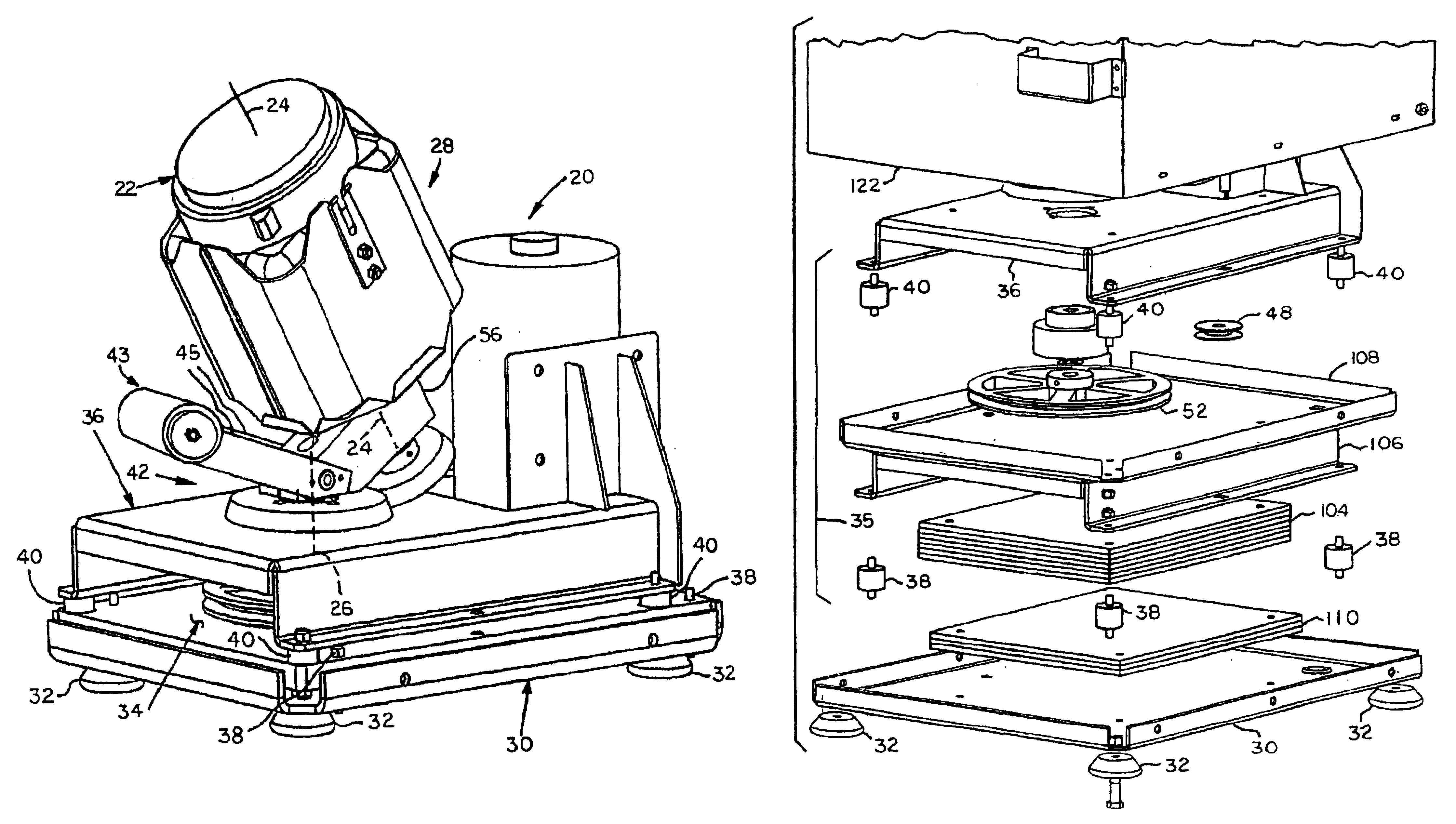
[0004]In accordance with the present invention, and apparatus is provided for vortex motion paint mixing machine of the type having a paint container holder spinning about its own axis and orbiting about a second axis positioned at an angle to the container axis, where the machine includes a base and a paint mixing apparatus having a drive mechanism to spin and orbit the paint container. The improvement in combination with the paint mixing machine includes an intermediate frame assembly located between the mixing apparatus and the base and secured therabetween by a plurality of vibration isolators. Also in accordance with the present invention, a method is provided for damping vibration in a paint mixing machine of the type capable of mixing paint in cylindrical or non-cylindrical containers. The method includes providing a receptacle for receiving one of a cylindrical and non-cylindrical paint container on a mixing apparatus; driving the receptacle with a spinning motion about an axis of the receptacle, and an orbiting motion about an axis separate from the axis of the receptacle; providing an intermediate frame between the mixing apparatus and a base; damping vibration between the intermediate frame and the mixing apparatus by a first vibration isolation system, and damping vibration between the intermediate frame and the base by a second vibration isolation system, such that vibration in the base caused by the paint container is reduced by the intermediate frame and the first and second vibration isolation systems.

Problems solved by technology

This new design of paint container results in a significant imbalance (because of the void created with the molded handle) when the paint container is subject to the orbital and spinning motion desirable for paint mixing.
When prior art mixers were attempted to be used with the rectangular paint container, unacceptable vibration resulted.

Method used


Image

  • Paint mixer with damping frame
  • Paint mixer with damping frame
  • Paint mixer with damping frame

Examples


Embodiment Construction

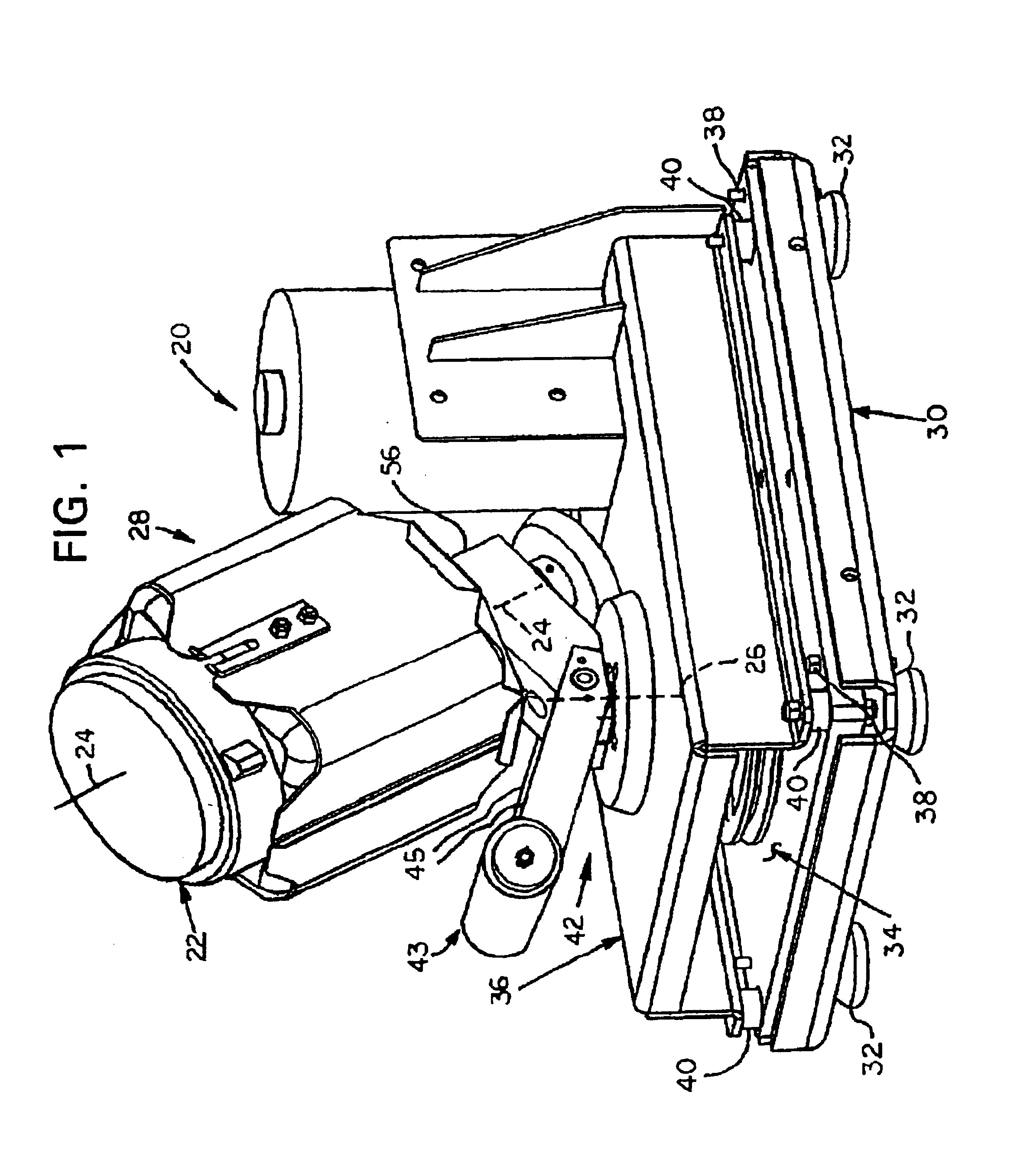
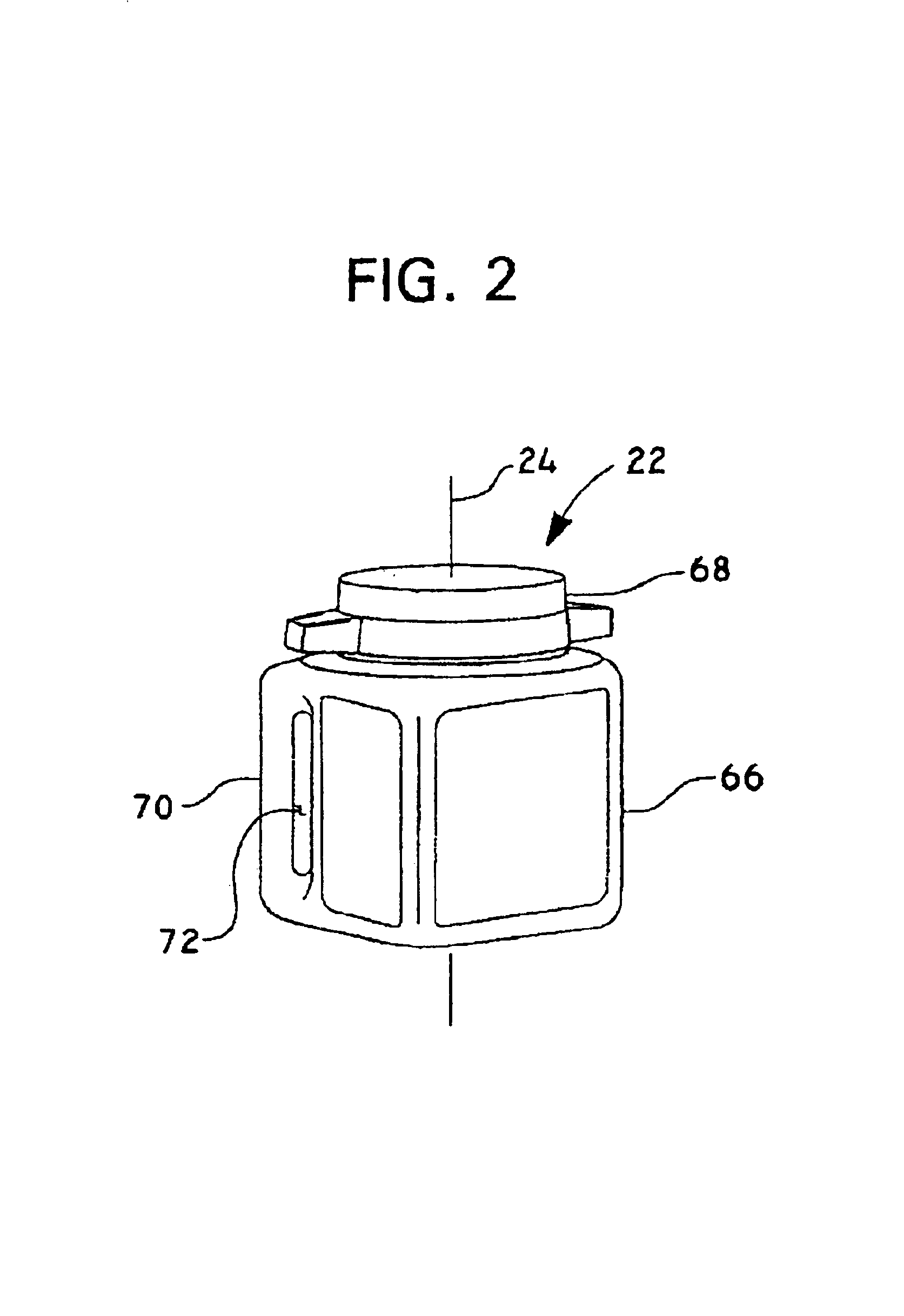
[0015]Referring to the Figures, and most particularly to FIGS. 1 and 3, a paint mixing machine or mixer 20 according to the present invention may be seen. Although not completely shown, it is to be understood that an enclosure is customarily provided to surround and fully enclose the mixer 20 shown in the drawings. The enclosure has a door for access to allow a user to insert and remove a paint container for mixing, and the mixer also preferably includes a door interlock switch and a timer, neither of which are shown herein. Mixer 20 rotates a paint container 22 about a first axis 24 (which is a central axis of the paint container), and planetates or orbits paint container 22 about a second axis 26. Paint container may be a conventional one gallon cylindrical paint can (not shown) or it may be a rectangular or square paint container 22, shown separately in FIG. 2. Mixer 20 has a paint container holder subassembly 28 (shown in an exploded view in FIG. 4). Holder 28 is arranged to be ...


PUM


Abstract

A paint mixing machine having at least two axes for spinning either of a cylindrical or rectangular paint container to mix the paint in the container. The machine includes a stationary base frame carrying a mixing apparatus and an intermediate frame between the stationary base frame and the mixing apparatus. The intermediate frame is connected to the mixing apparatus and the stationary base frame by a plurality of vibration isolators. The intermediate frame includes damping weight to balance the deflection of the damping isolators. The base may also include one or more damping weights.

Description

BACKGROUND OF THE INVENTION[0001]The present invention relates to the field of paint mixing, particularly machines for mixing paint in retail-sized containers, most particularly to those machines which spin the paint container on more than one axis.[0002]In the past, paint has been uniformly sold in the United States at the retail level in one gallon cylindrical cans or containers. Certain prior art paint mixers were designed for mixing custom colors of paint in such one gallon cylindrical containers, using both orbital and spinning motion with the cylindrical container held at an angle during paint mixing operation. Recently paint has become available in a square or rectangular shaped polymer container which has a handle molded integrally into one corner of the container for the painter's convenience in pouring paint from the rectangular container. This new design of paint container results in a significant imbalance (because of the void created with the molded handle) when the pai...

Claims


Application Information

Patent Timeline
IPC IPC(8): B01F15/00B01F9/00F16F15/08F16F15/22
CPCB01F9/0001B01F15/0074F16F15/08F16F15/22B01F2215/005B01F29/10B01F35/421B01F2101/30
Inventor MIDAS, THOMAS J.CURTIS, AARON
Owner RED DEVIL EQUIP
Learn More