
Ring airfoil launcher toy with safety features

a safety feature and launcher technology, applied in the field of ring airfoil launchers, can solve the problems of affecting the safety of the airfoil, the airfoil to have significantly less in-flight stability, and it took a number of years for the ring airfoil to be successfully adapted to toy and sporting good applications, so as to reduce the risk of injury, prevent jabs, and stabilize the spin

Inactive Publication Date: 2005-10-11
FLATAU & VANEK
View PDF6 Cites 10 Cited by
  • Summary
  • Abstract
  • Description
  • Claims
  • Application Information

AI Technical Summary

Benefits of technology

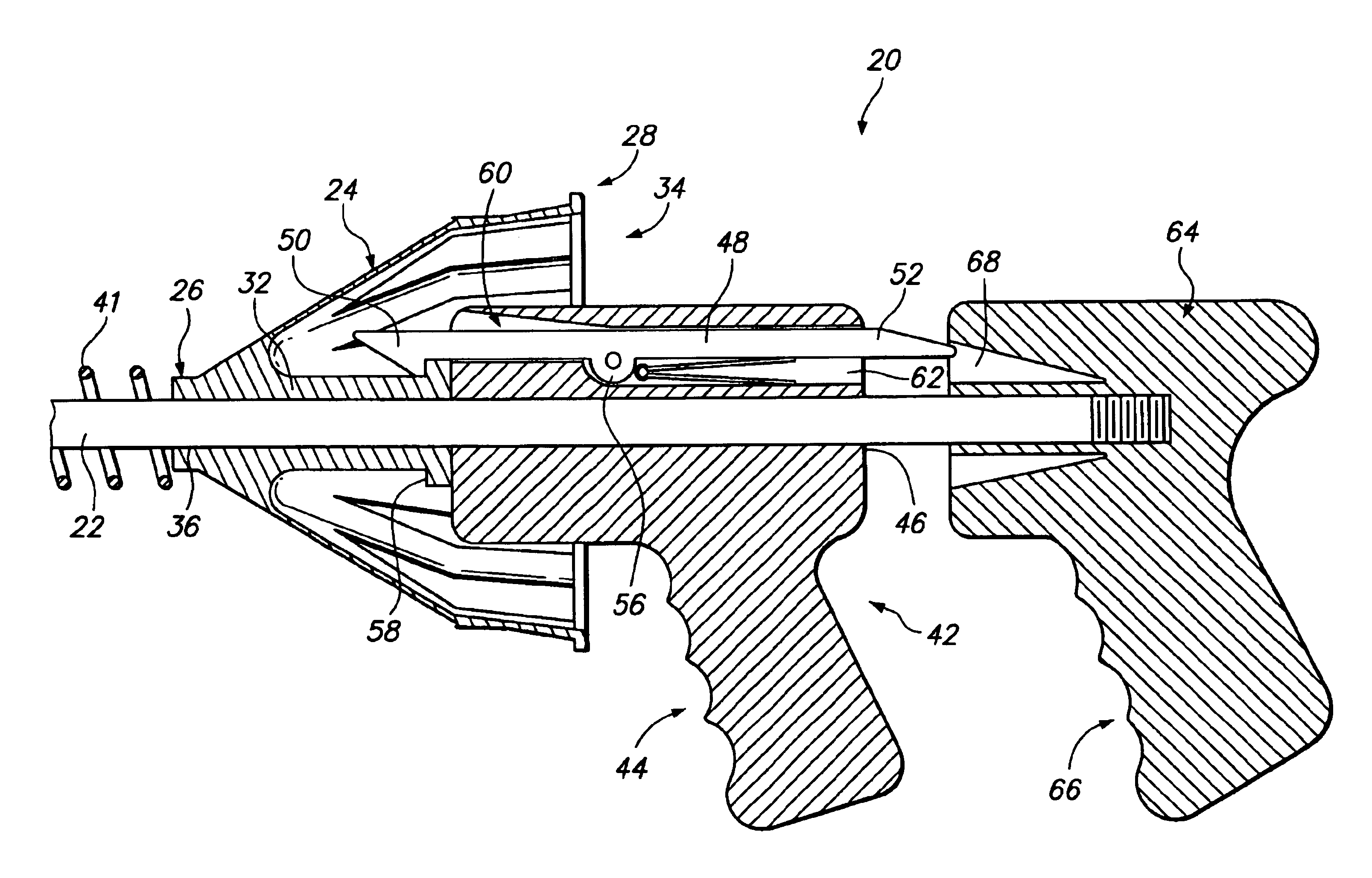
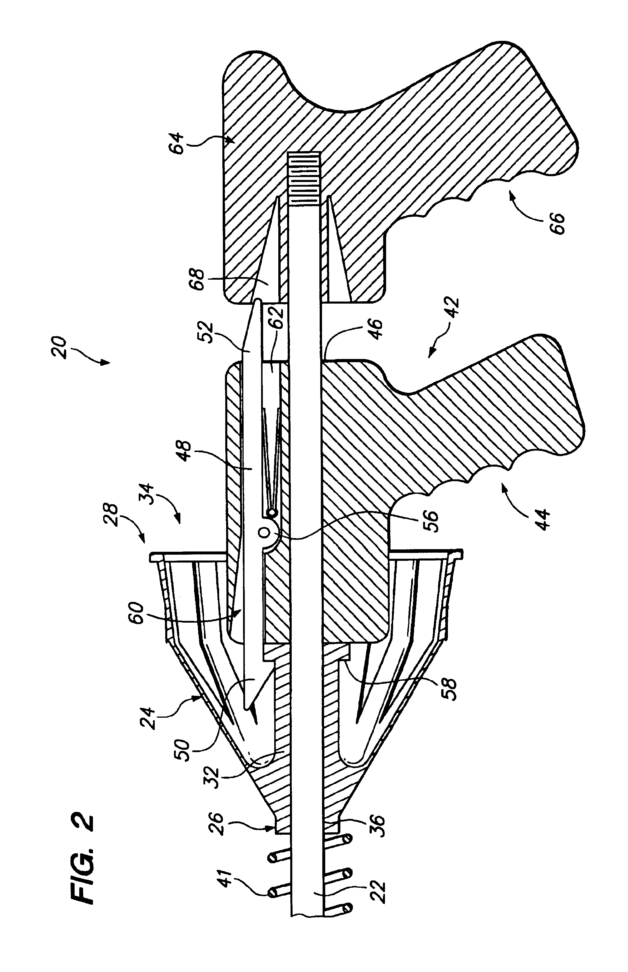
"The invention is a ring airfoil launcher and a method of launching a ring airfoil. The launcher is designed for use as a toy or in similar sporting environments. It includes a main support with a chuck for holding the ring airfoil, a stop for limiting the movement of the chuck, a motive force for the chuck, a retractor for selectively connecting to the chuck, and a connector for disengaging the chuck. The launcher has safety features and advantages such as a safety cap, a smooth chuck shape, and a zero angle of attack. The amount of spin and direction of spin can be custom-selected by the user. The technical effects of the invention are a launcher that effectively launches a ring airfoil with forward velocity and stabilizing spin, and a method for safely and efficiently launching a ring airfoil."

Problems solved by technology

However, it took a number of years before the ring airfoil was successfully adapted to toy and sporting good applications.
One significant drawback to the launcher just described is that the amount of spin which can be imparted on the airfoil is very limited, causing the airfoil to have significantly less in-flight stability.
Thus, only a very limited amount of rotational force can be generated by the bands, that force limited to that which is generated by offsetting the ends of each band by less than 180 degrees about the member.
Other problems include the fact that when the chuck is released, it also moves the draw-string forward in a sharp motion.

Method used


Image

  • Ring airfoil launcher toy with safety features
  • Ring airfoil launcher toy with safety features
  • Ring airfoil launcher toy with safety features

Examples


Embodiment Construction

[0027]The invention is a ring airfoil launcher, and more particularly a ring airfoil launching toy having safety features. In the following description, numerous specific details are set forth in order to provide a more thorough description of the present invention. It will be apparent, however, to one skilled in the art, that the present invention may be practiced without these specific details. In other instances, well-known features have not been described in detail so as not to obscure the invention.

[0028]In general, the invention is a ring airfoil launcher. The launcher includes a chuck movable along a guide member. A cocking mechanism is configured to engage the chuck for movement into a retracted, twisted position. When released, the chuck moves forward while rotating, thus imparting significant forward velocity and spin upon a ring airfoil mounted on the chuck. As one aspect of the invention, the amount of velocity and spin which is imparted upon the ring airfoil can be cust...


PUM


Abstract

A ring airfoil launcher comprises a main support on which is movably mounted a ring airfoil accepting conical chuck and a retractor. A stop mounted on the main support for limiting forward movement of the chuck. A spring biases the chuck towards the stop. The retractor is mounted distal of the chuck and includes a latch for connecting it to the chuck. Rearward movement of the retractor causes rearward movement of the chuck, extending said spring. Twisting of the retractor rotates the chuck, winding the spring. A release disengages the latch from the chuck, allowing the spring to pull the chuck forward along the main support towards the stop, and rotating the chuck as it unwinds, causing the ring airfoil mounted on said chuck to be released from the launcher with forward velocity and stabilizing spin.

Description

RELATED APPLICATION[0001]This application claims priority to U.S. Provisional Application Ser. No. 60 / 467,594, filed May 2, 2003.FIELD OF THE INVENTION[0002]The present invention relates to ring airfoil launchers.BACKGROUND OF THE INVENTION[0003]Projectile launching toys are an age old favorite. Toys which launch discs, balls and other elements are well known.[0004]The ring airfoil is a relatively new flying device in the field of toys and sporting goods. Ring airfoils are known in military and similar applications. However, it took a number of years before the ring airfoil was successfully adapted to toy and sporting good applications. In particular, a variety of factors must be addressed in order for a ring airfoil to be successfully launched with stable flight characteristics. These factors include launch velocity, spin-to-translation ratio, and angle of attack.[0005]The first successful ring airfoil launching toy was the Vortex Tornado. This launcher is described in U.S. Pat. No...

Claims


Application Information

Patent Timeline
Patent Type & Authority Patents(United States)
IPC IPC(8): F41B7/08F41B7/00
CPCF41B7/00F41B7/08
Inventor VANEK, CHESTER F.FLATAU, ABRAHAM
Owner FLATAU & VANEK
Learn More