
Vertical MEMS gyroscope by horizontal driving

a vertical driving and gyroscope technology, applied in the direction of electromagnetic relay details, acceleration measurement using interia forces, turn-sensitive devices, etc., can solve the problems of adherence of the motion electrode and the fixed electrode, degradation of reliability and performance, and cost increas

Active Publication Date: 2005-10-11
SAMSUNG ELECTRONICS CO LTD
View PDF7 Cites 37 Cited by
  • Summary
  • Abstract
  • Description
  • Claims
  • Application Information

AI Technical Summary

Benefits of technology

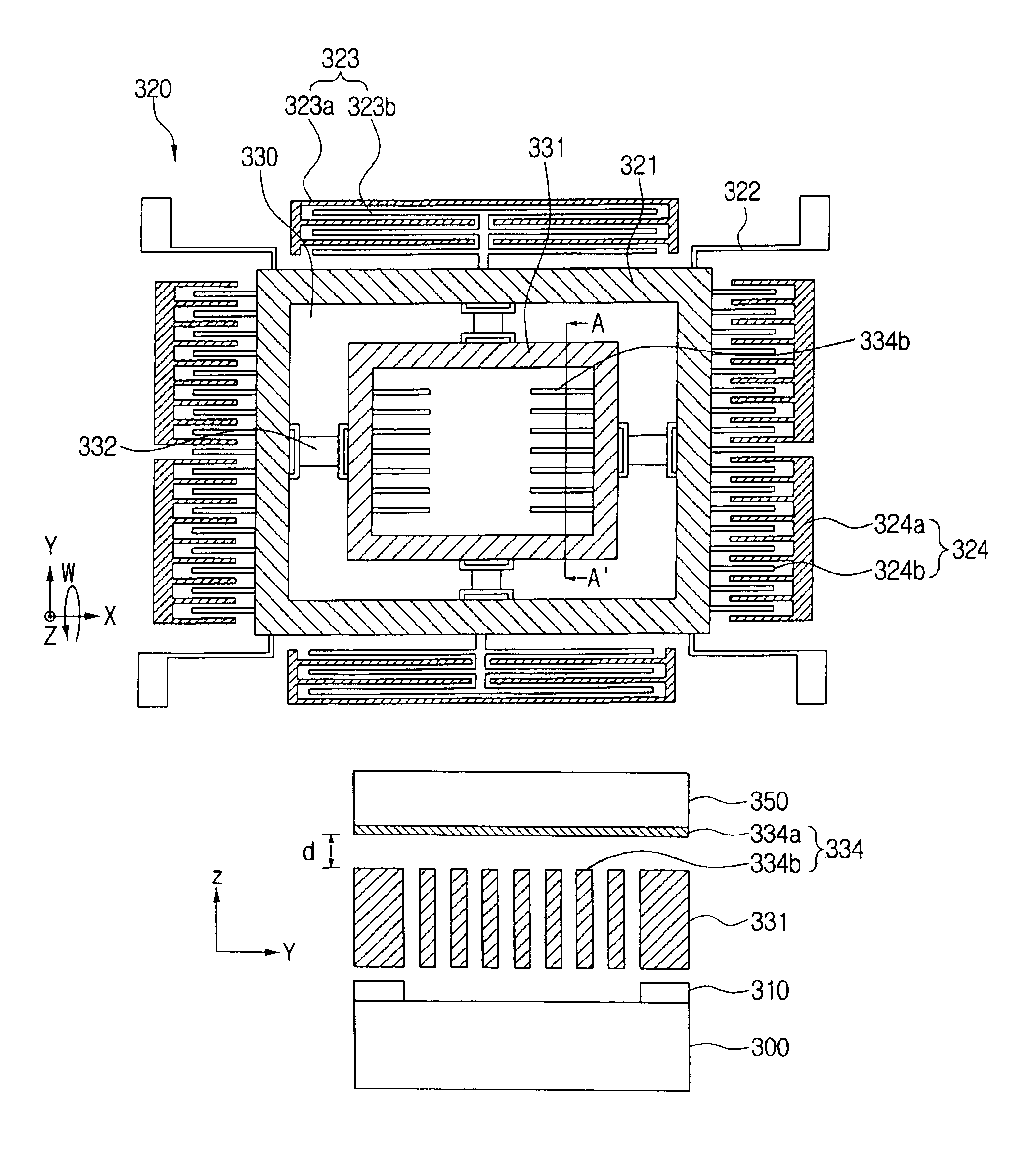
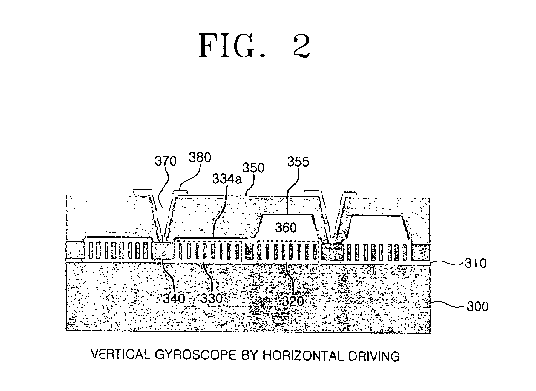
The present invention provides a vertical MEMS gyroscope by horizontal driving and a fabricating method thereof. The vertical MEMS gyroscope includes a substrate, a support layer, a driving structure, and a detecting structure. The driving structure has a predetermined area capable of vibrating in a predetermined direction parallel to the substrate, while the detecting structure has a predetermined area capable of vibrating in a vertical direction with respect to the substrate. The detecting structure includes a detection mass and a motion vertical displacement detection electrode for measuring displacement of the detecting structure in the vertical direction. The fabricating method involves forming a structure wafer and a cap wafer, anodic-bonding them together, and forming an external electrode that is electrically connected with the fixed vertical displacement detection electrode. The vertical MEMS gyroscope has the advantage of being able to detect displacement in both the horizontal and vertical directions.

Problems solved by technology

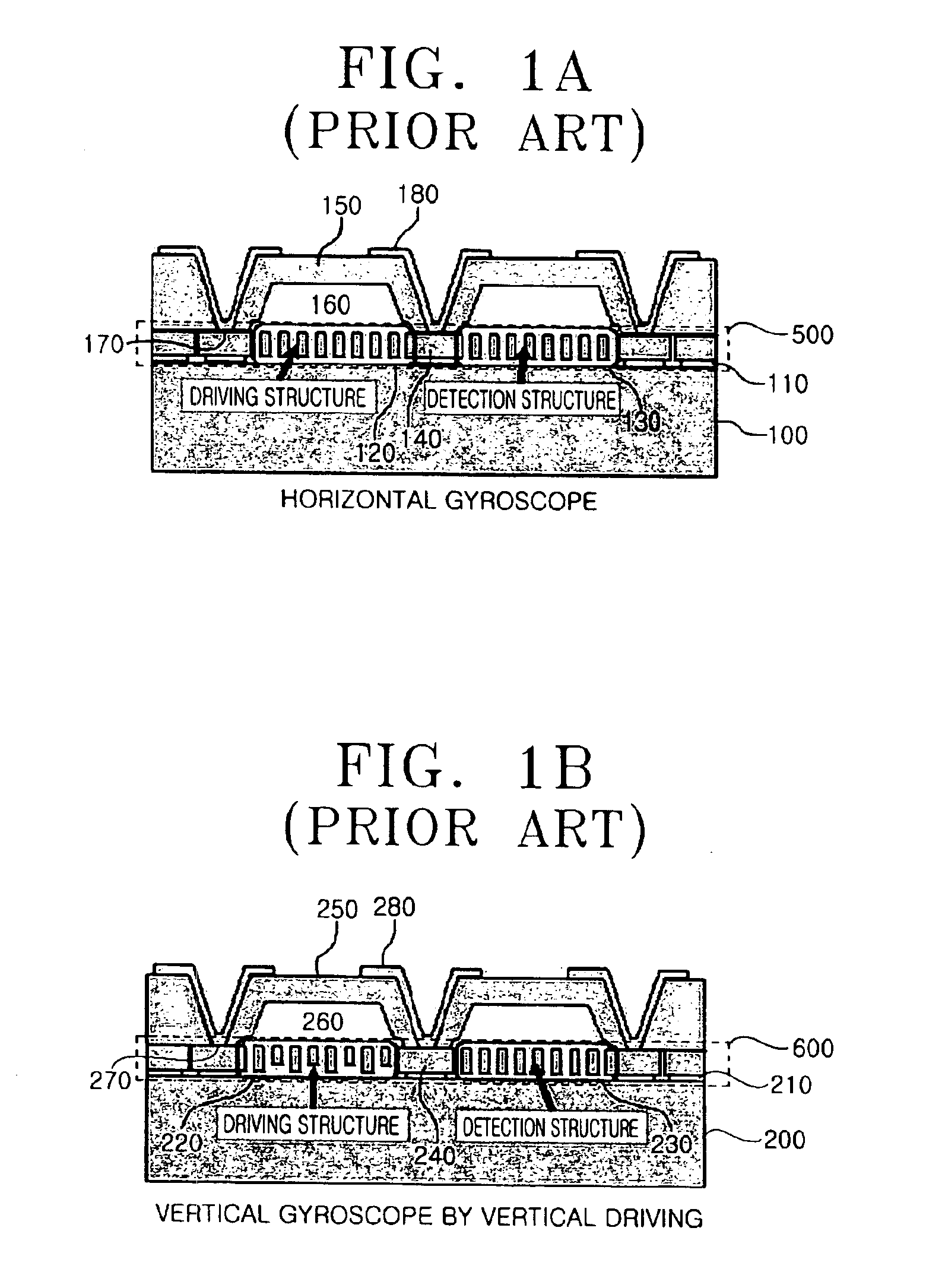
Accordingly, in order to measure multiple-axis angular velocity, a process of arranging an element vertically is additionally required, which causes a considerable increase in cost, as well as degradation in reliability and performance.
However, this may cause an adherence of the motion electrode and the fixed electrode.
Accordingly, a fabrication process becomes complicated, and a vertical MEMS gyroscope cannot be fabricated together with a horizontal MEMS gyroscope.
Further, when the driving mass is driven vertically by the driving electrode formed at the side of the driving mass, the displacement of the driving mass is non-linear.

Method used


Image

  • Vertical MEMS gyroscope by horizontal driving
  • Vertical MEMS gyroscope by horizontal driving
  • Vertical MEMS gyroscope by horizontal driving

Examples


Embodiment Construction

[0037]Korean Patent Application No. 2002-82983, filed on Dec. 24, 2002, and entitled: “Vertical Mems Gyroscope By Horizontal Driving And Fabrication Method Thereof” is incorporated by reference herein in its entirety.

[0038]The present invention will now be described more fully hereinafter with reference to the accompanying drawings, in which preferred embodiments of the invention are shown. The invention may, however, be embodied in different forms and should not be construed as limited to the embodiments set forth herein. Rather, these embodiments are provided so that this disclosure will be thorough and complete, and will fully convey the scope of the invention to those skilled in the art. In the drawings, the thickness of layers and regions are exaggerated for clarity. Like reference numerals refer to like elements throughout.

[0039]FIG. 2 illustrates a schematic sectional view showing a vertical MEMS gyroscope by horizontal driving according to an embodiment of the present invent...


PUM

PropertyMeasurementUnit
thicknessaaaaaaaaaa
frequencyaaaaaaaaaa
temperatureaaaaaaaaaa

Abstract

A vertical MEMS gyroscope by horizontal driving includes a substrate, a support layer fixed on an upper surface of an area of the substrate, a driving structure floating above the substrate and having a portion fixed to an upper surface of the support layer and another portion in parallel with the fixed portion, the driving structure having a predetermined area capable of vibrating in a predetermined direction parallel to the substrate, a detecting structure fixed to the driving structure on a same plane as the driving structure, and having a predetermined area capable of vibrating in a vertical direction with respect to the substrate, a cap wafer bonded with the substrate positioned above the driving structure and the detecting structure, and a fixed vertical displacement detection electrode formed at a predetermined location of an underside of the cap wafer, for detecting displacement of the detecting structure in the vertical direction.

Description

BACKGROUND[0001]1. Field of the Invention[0002]The present invention relates to a micro electro-mechanical system (MEMS) gyroscope for measuring rotational angular velocity of various devices. More particularly, the present invention relates to a vertical MEMS gyroscope by horizontal driving in which motions of a driving mass and detection mass are performed independently of each other.[0003]2. Description of the Related Art[0004]Gyroscopes, well known for rotational angular velocity detection, have been widely used in many areas, and are particularly important as a core part of navigation equipment in ships and airplanes. Nowadays, the development of the gyroscope has enabled application of the same in areas such as navigation systems for automobiles and hand-tremor compensation devices for high-resolution video cameras.[0005]Gyroscope operation is based on the Coriolis force. When there is a certain mass vibration in a certain direction, say, in a direction of a first axis, and a ...

Claims


Application Information

Patent Timeline
Patent Type & Authority Patents(United States)
IPC IPC(8): B81B3/00B81C1/00G01C19/56B81B7/00B81B5/00G01C19/5762G01C19/5769
CPCB81B3/0059G01C19/5762B81B2201/0242B81B2203/051B81B2203/053B81B7/00
Inventor KANG, SEOK-JINCHUNG, SEOK-WHANLEE, MOON-CHULJUNG, KYU-DONGHONG, SEOG-SOO
Owner SAMSUNG ELECTRONICS CO LTD
Learn More