
Ice making machine

a technology of ice making machine and ice maker, which is applied in the direction of ice production, defrosting, domestic cooling apparatus, etc., can solve the problem that the conventional ice making machine cannot be located only at places, and achieve the effect of less water supply and discharg

Inactive Publication Date: 2005-10-11
SAMSUNG GWANGJU ELECTRONICS CO LTD
View PDF8 Cites 33 Cited by
  • Summary
  • Abstract
  • Description
  • Claims
  • Application Information

AI Technical Summary

Benefits of technology

[0014]Accordingly, the present invention has been made to solve the above-mentioned problems occurring in conventional ice making machines, and an aspect of the present invention is to provide an ice making machine which is designed to require less supply and discharge of water and to include a feed water receptacle and a drain receptacle, which may take the form of buckets, within a housing thereof so that it can continuously operate for several days, without the need to be managed by an operator, and can be installed at any place, even where a direct water supply line or drainage are not readily available.

Problems solved by technology

However, such a conventional ice making machine can only be located at places where it can be connected to an external water supply line for supplying water to the freezing unit and where drainage for discharging a great amount of unfrozen water is available.

Method used


Image

  • Ice making machine
  • Ice making machine
  • Ice making machine

Examples


first embodiment

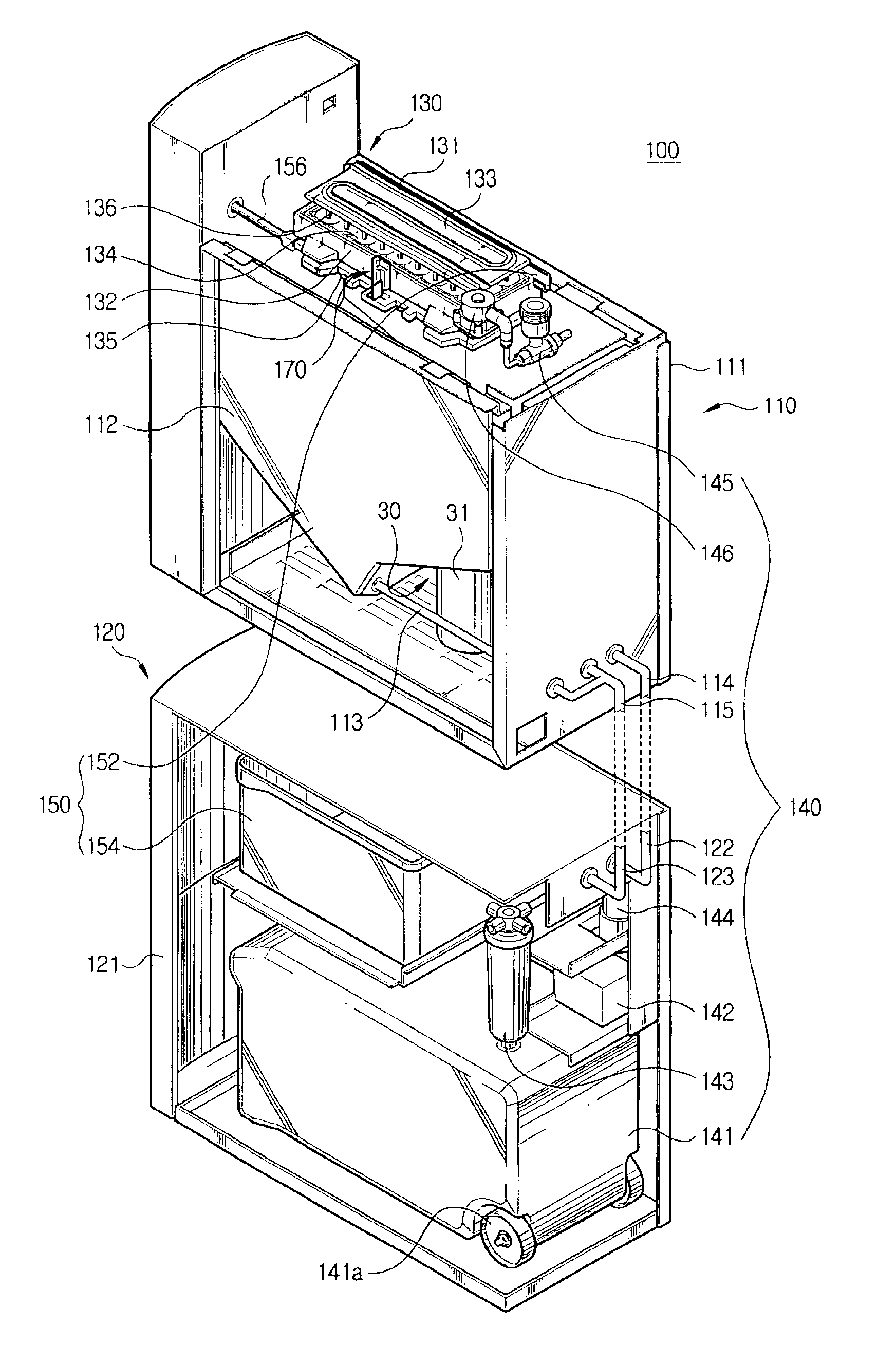
[0034]As illustrated in FIG. 3, an ice making machine 100 according to the present invention is comprised of a main body 110 and an auxiliary table 120 separably connected to the main body 110. More specifically, the ice making machine 100 comprises an upper housing 111 for receiving the main body 110, a lower housing 121 for receiving the auxiliary table 120, a freezing unit 130 for making ice by freezing supplied water, a water supply system 140 for supplying water to the freezing unit 130 and a drain system 150 for discharging water remaining in the freezing unit 130.

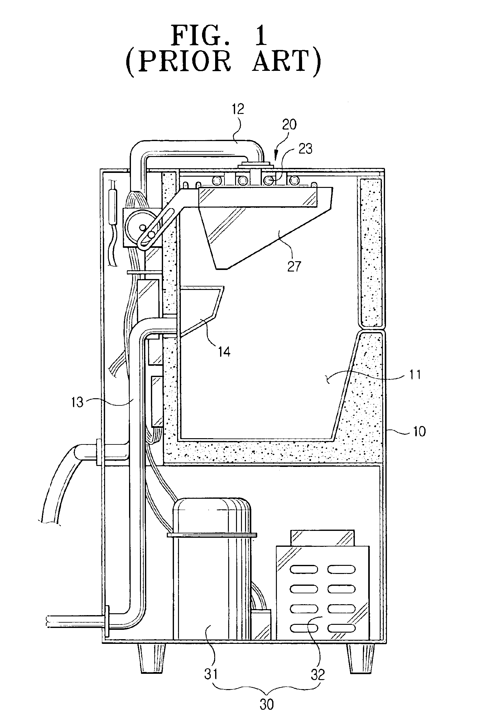
[0035]The upper housing 111 contains a cooling system 30 including a compressor 31 and a condenser 32, as in the conventional ice making machine illustrated in FIG. 1. The upper housing 111 also includes a freezing unit 130 for making ice from supplied water and an ice bin 112 for storing the ice pieces made by the freezing unit 130. The lower housing 121 contains a feed water receptacle 141 and a drain receptacle 15...

second embodiment

[0055]FIG. 7 shows another ice making machine according to the present invention.

[0056]As shown in FIG. 7, an ice making machine 200 according to the second embodiment is similar in structure to the ice making machine 100, according to the first embodiment. However, the ice making machine 200 is different in that it has a freezing unit 220, a cooling system 230, a water supply system 240 and a drain system 260, all disposed in a single housing 210 having upper and lower chambers 211 and 212 therein.

[0057]The upper chamber 211 includes the freezing unit 220 for forming ice by freezing supplied water, the cooling system 230 connected to the freezing unit 220 and an ice bin 213 for storing ice pieces formed by the freezing unit 220.

[0058]The lower chamber 212 comprises the water supply system 240, which includes a feed water receptacle 241, a water supply pump 242, a water purifier 243 and a sterilizing light 244. The lower chamber 212 also includes the drain system, including a drain ...


PUM


Abstract

An ice making machine having a main body and an auxiliary table which is separable from the main body, wherein the main body of the ice making machine comprises a freezing unit for making ice pieces by freezing water separated into discrete cells; a cooling system connected to the freezing unit; an ice bin for storing ice pieces made by the freezing unit; a first water supply pipe for supplying water to the freezing unit; and a first drain pipe for discharging water remaining unfrozen in the freezing unit. The auxiliary table comprises a feed water receptacle and a drain receptacle, both having a space for containing a predetermined level of water; a second water supply pipe selectively connected to the first water supply pipe to supply water contained in the feed water receptacle to the freezing unit; and a second drain pipe selectively connected to the first drain pipe to direct water discharged from the freezing unit to flow to the drain receptacle. The first water supply pipe and first drain pipe of the main body can be selectively and respectively connected to an external water line for supplying water and an external drainage for discharging water remaining unfrozen in the freezing unit.

Description

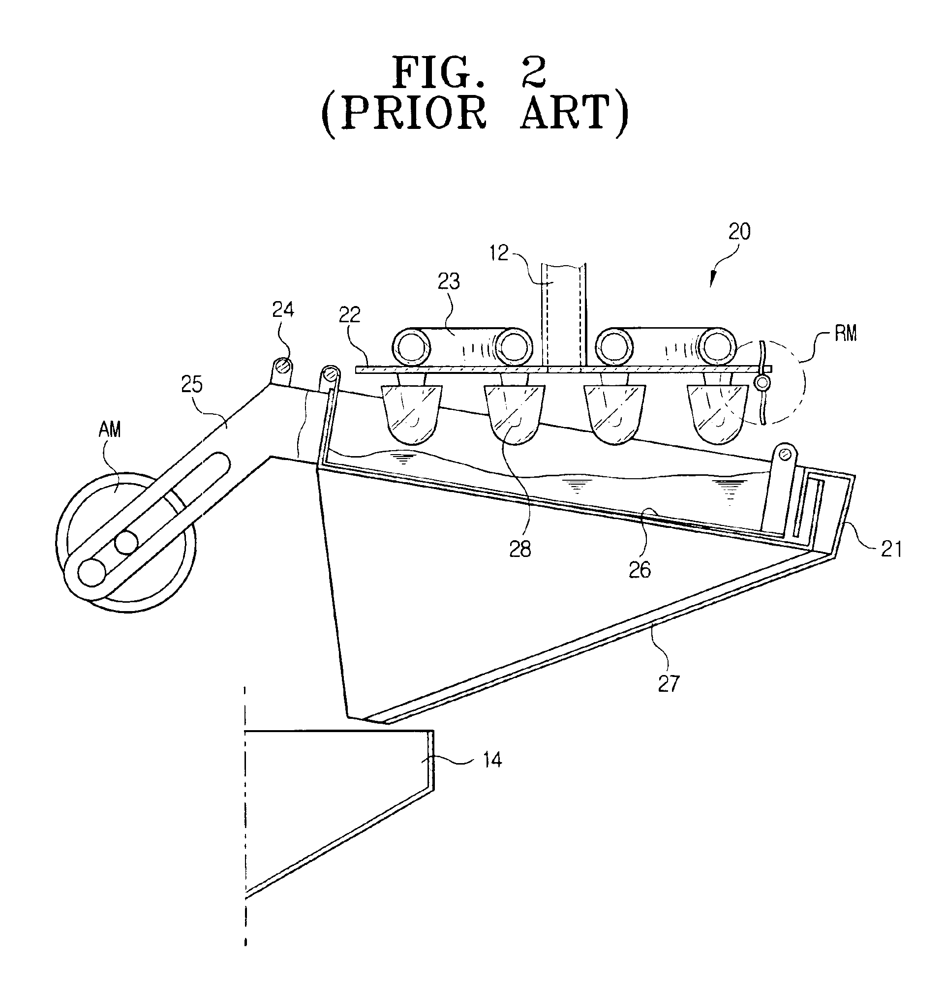
BACKGROUND OF THE INVENTION[0001]1. Field of the Invention[0002]The present invention relates generally to ice making machines, and more particularly to an ice making machine having a feed water receptacle and a drain receptacle within a housing thereof so that it can be installed any where that is desired, irrespective of availability of a water source.[0003]2. Description of the Related Art[0004]As is generally known in the art, an ice making machine is used to make ice by freezing water supplied to the machine from an external source. FIG. 1 illustrates a conventional ice making machine, such as that disclosed in U.S. Pat. No. 5,425,243.[0005]As shown in FIG. 1, the conventional ice making machine comprises a housing 10 and a freezing unit 20.[0006]The housing 10 includes an ice bin 11 disposed therein to store ice pieces formed in the freezing unit 20. A cooling system 30 including a compressor 31 and a condenser 32 is provided below the ice bin 11. A water supply pipe 12 for su...

Claims


Application Information

Patent Timeline
Patent Type & Authority Patents(United States)
IPC IPC(8): F25C1/08F25C1/12F25C1/22
CPCF25C1/08F25C1/225F25C2400/12F25C2400/14F25D2323/122F25C1/25F25C1/22
Inventor CHOI, CHEOL-HONAKAJO, HIDEO
Owner SAMSUNG GWANGJU ELECTRONICS CO LTD
Learn More