
Multi-purpose mobile cordless phone system

a multi-purpose, cordless phone technology, applied in the direction of wireless communication, call diverting means, wireless communication, etc., can solve the problems of cordless phone systems with similar functionality and comparable overall cost, and achieve the effect of low cos

Inactive Publication Date: 2005-09-27
POLUTEK
View PDF11 Cites 78 Cited by
  • Summary
  • Abstract
  • Description
  • Claims
  • Application Information

AI Technical Summary

Benefits of technology

[0012]According to the present invention, a mobile transponder unit can be physically connected to a base station and, hence, it is not necessary for the latter to incorporate a radio transceiver. In other words, the system includes similar functionality to typical stand-alone mobile and cordless phone systems but at a comparable overall cost. In view of this, one objective of the multi-purpose mobile cordless phone system is to provide low cost means for communication between the mobile transponder unit and a local-loop connection of a fixed telephone network.
[0020]The inclusion of an enhanced image display screen, PDA electronics and a QWERTY keyboard within the multi-purpose mobile cordless phone system make the latter suitable for use within a Local Area Network (LAN). Under these circumstances, the physical connection of the mobile transponder unit to a LAN interface can provide an even higher bandwidth of 10-100 Mbit / s (for example, when the Ethernet bus is used) for visual image signals. On the other hand, if the QWERTY keyboard is incorporated within the cordless phone, signals can pass to the transponder unit at a more than adequate rate by using a Bluetooth radio link (less than 1 Mbit / s). An eight objective of the present invention is thus to provide a low cost client for a LAN server.

Problems solved by technology

In other words, the system includes similar functionality to typical stand-alone mobile and cordless phone systems but at a comparable overall cost.
However, the only fully automatic diversion option presently available to the latter involves the provision of a personal contact number via a telecom service provider, which thus normally attracts a premium rate charge.

Method used


Image

  • Multi-purpose mobile cordless phone system
  • Multi-purpose mobile cordless phone system
  • Multi-purpose mobile cordless phone system

Examples


Embodiment Construction

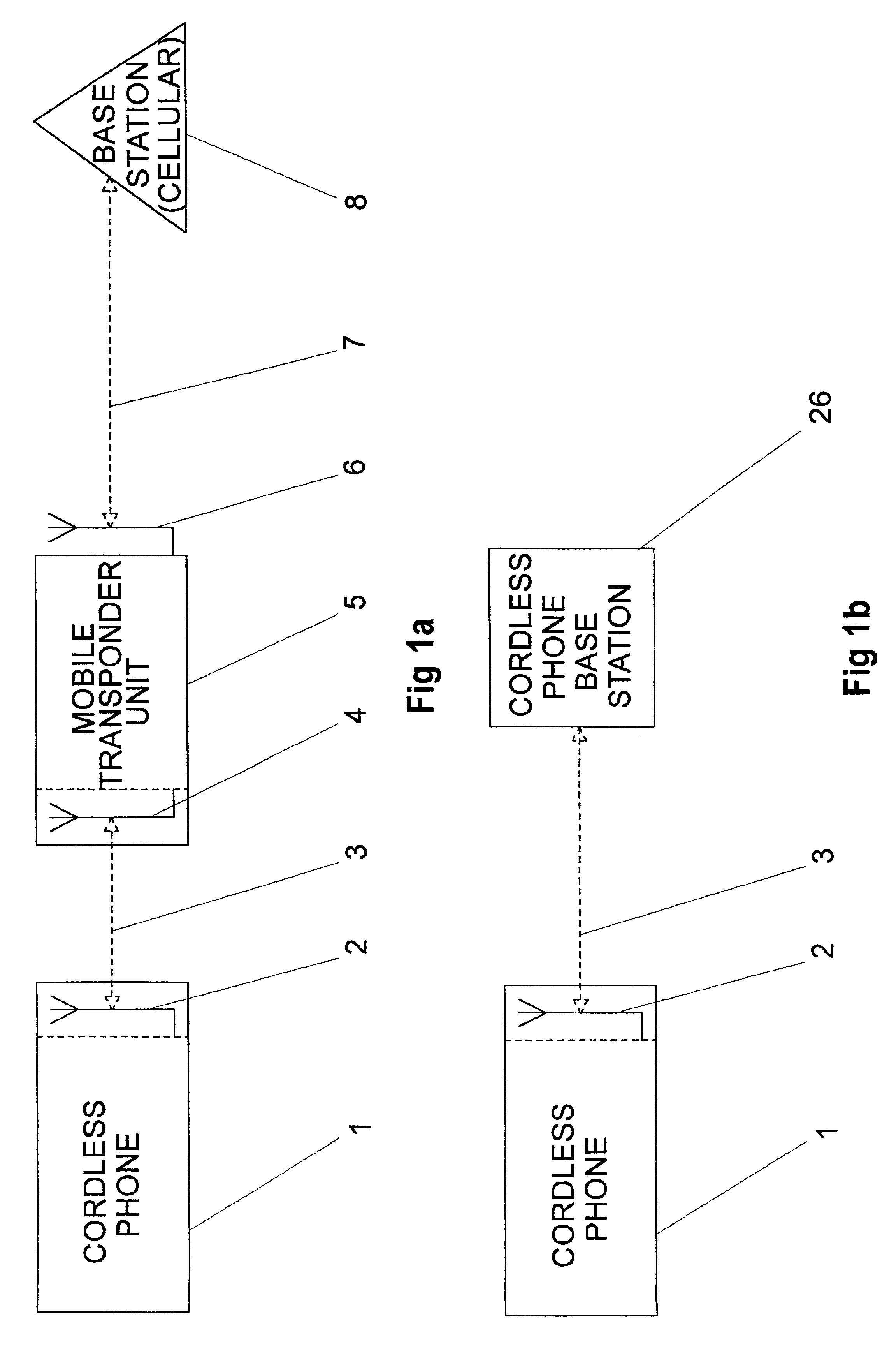
[0044]Referring to the prior art shown in FIG. 1a, a cordless phone 1 transmits and receives via internal antenna 2, passing low powered signals 3 to and from the mobile transponder unit 5 via internal antenna 4. On the other hand, the mobile transponder unit 5 communicates with a cellular network base station 8 via external antenna 6, transmitting and receiving the high powered signals 7.

[0045]Referring to FIG. 1b, the cordless phone 1 can alternatively transmit and receive via internal antenna 2, passing low power signals 3 to and from a cordless phone base station 26. The phone 1 and transponder 5 incorporate existing cordless and mobile phone technology, each powered by their respective rechargeable battery packs. For example, phone 1 uses technology based on the DECT cordless phone standard to communicate with transponder 5 or selectively communicate with cordless phone base station 26. On the other hand, the transponder 5 might incorporate technology based on the widely used G...


PUM


Abstract

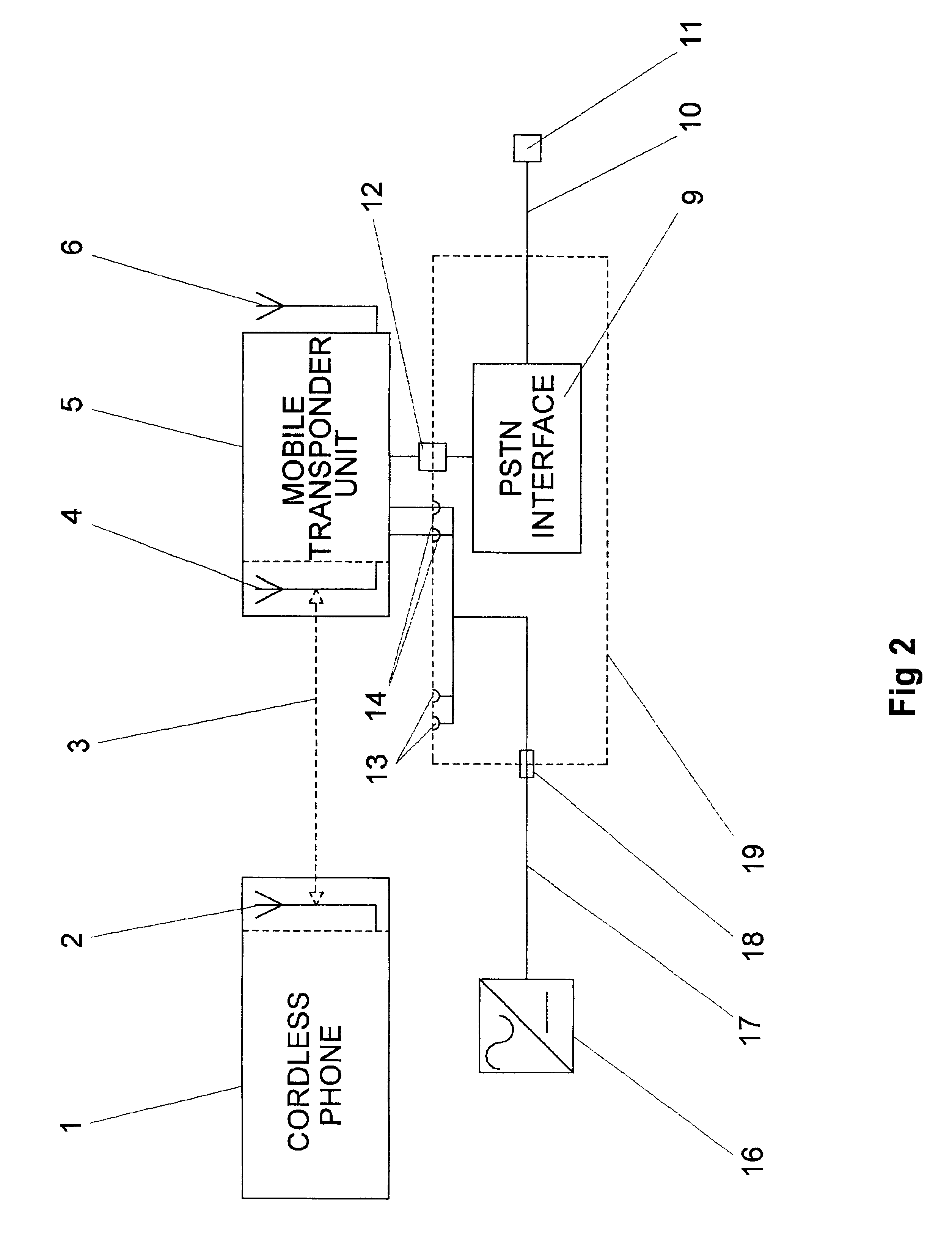
A cordless phone 1 is able to communicate signals 3 via antenna 2 and 3 with transponder unit 5. When the transponder 5 is physically connected (as shown) via multi-way connector 12 to base station 19, the system communicates via PSTN interface 9 and cable 10 connected to local-loop socket 11 within a fixed telephone network. When the transponder 5 is disconnected (not shown) from base station 19, the system communicates via external antenna 6 by radio link with a local base station within a cellular phone network. The base station 19 provides means to recharge the batteries (not shown) of cordless phone 1 via connectors 13 and transponder unit 5 via connectors 14, with dc supply being provided by power plug 16 via cable 17. The transponder unit may include a display screen and PDA electronics (not shown), or, be incorporated within a portable computer (not shown).

Description

CROSS REFERENCE TO RELATED APPLICATIONS[0001]GB 0001754.1 filed in the UK on 27 Jan. 2000[0002]GB 0019189.0 filed in the UK on 7 Aug. 2000[0003]GB 0023256.1 filed in the UK on 21 Sep. 2000[0004]GB 0024341.0 filed in the UK on 5 Oct. 2000STATEMENT REGARDING FEDERALLY SPONSORED RESEARCH AND DEVELOPMENT[0005]Not ApplicableBACKGROUND TO THE INVENTION[0006]The present invention relates to a multi-purpose mobile cordless phone system, including means to allow a cordless phone to selectively communicate either via a local base station of a cellular phone network or via a local-loop connection of a fixed telephone network.[0007]Throughout the following description and claims, the words “mobile phone” and “cordless phone” are used as generic terms for any compact portable device (for example, handheld phones, wrist phones, wearable phones incorporated into clothing) suitable for personal communication of voice / sound, data and / or visual image signals via a radio link.[0008]It is well known th...

Claims


Application Information

Patent Timeline
IPC IPC(8): H04M1/725H04M1/72H04M1/00H04Q7/32H04M1/02H04W88/02
CPCH04M1/006H04M1/725H04W88/02H04M1/0202H04M2250/02H04M2250/08
Inventor JARRETT, PHILLIP
Owner POLUTEK
Learn More