
Design and fabrication process for a lens system optically coupled to an image-capture device

a technology of optical coupling and image capture, applied in the field of electronic imaging, can solve the problems of reducing the complexity of the lens system, increasing the complexity (and the cost) of the lens, and the optical combination is not significantly simplified, so as to achieve simple and durable multi-element optical systems

Inactive Publication Date: 2005-09-27
SAYAG MICHEL
View PDF14 Cites 6 Cited by
  • Summary
  • Abstract
  • Description
  • Claims
  • Application Information

AI Technical Summary

Benefits of technology

This patent describes how to create small but durable optical systems that can send out light. One part of this system consists of two rounded pieces of glass that have a special coating on their surfaces. Another part of the system has a curved surface with another layer of coating. These parts work together to direct some of the light sent through them in different directions. Overall, these designs help make better quality optics more easily than before.

Problems solved by technology

The technical problem addressed in this patent is how to efficiently and easily assemble multiple glass lens elements together with an image-capture device without increasing the complexity of the lens system or requiring expensive equipment. Current methods involve time-consuming steps like focusing the lens system onto the sensor and reducing the complexities of individual lens elements but fail to simplify the process of combining them into a complete system. There is also a preference for higher performing materials like glass over plastic due to limitations in achieving high surface quality needed for optimal performance.

Method used


Image

  • Design and fabrication process for a lens system optically coupled to an image-capture device
  • Design and fabrication process for a lens system optically coupled to an image-capture device
  • Design and fabrication process for a lens system optically coupled to an image-capture device

Examples


Embodiment Construction

[0043]Reference will now be made in detail to specific embodiments of the invention including the best modes contemplated by the inventors for carrying out the invention. Examples of these specific embodiments are illustrated in the accompanying drawings. While the invention is described in conjunction with these specific embodiments, it will be understood that it is not intended to limit the invention to the described embodiments. On the contrary, it is intended to cover alternatives, modifications, and equivalents as may be included within the spirit and scope of the invention as defined by the appended claims. In the following description, specific details are set forth in order to provide a thorough understanding of the present invention. The present invention may be practiced without some or all of these specific details. In addition, well known features may not have been described in detail to avoid unnecessarily obscuring the invention.

[0044]Multi-element glass lens systems a...


PUM


Abstract

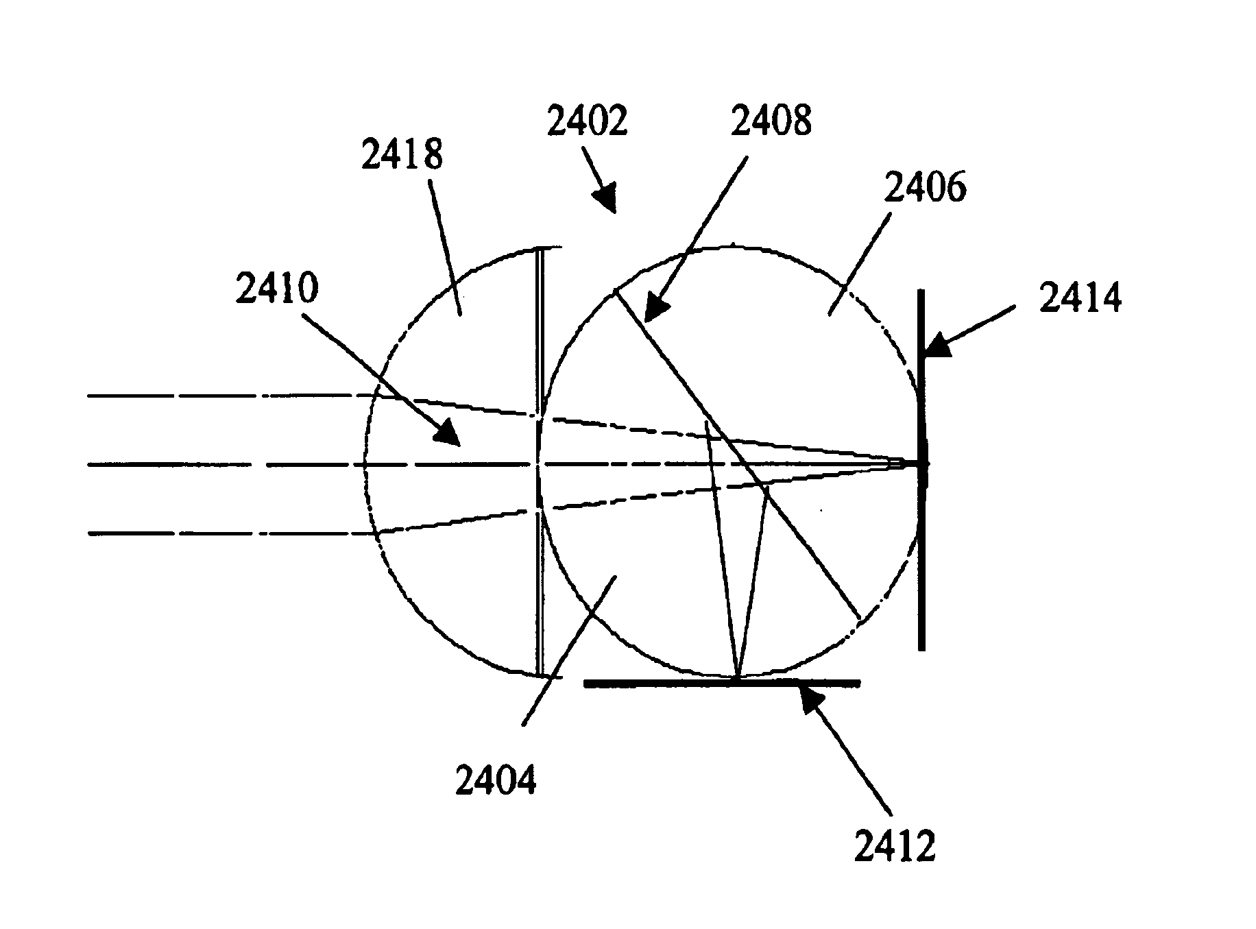
An optical system operable to transmit an energy flux is described. A first substantially spherical lens includes first and second substantially hemispherical portions joined at an interface. The interface includes a partially reflective material on a first substantially planar surface of at least one of the first and second hemispherical portions. A second lens has a convex surface and a second substantially planar surface. A portion of the second substantially planar surface of the second lens is secured to the first lens to form an optical axis. The first and second lenses are operable to transmit a first portion of the energy flux along the optical axis. The partially reflective surface is operable to reflect a second portion of the energy flux at an angle to the optical axis.

Description


Claims


Application Information

Patent Timeline
Owner SAYAG MICHEL
Learn More