
Multi-spectral color correction

a color correction and multi-spectral technology, applied in the field of computer graphics, can solve the problems of exacerbated non-repeatability of color between units, affecting the performance of color filters, and changing the filtering characteristics of absorbent materials in color filters, so as to increase the memory storage and processing bandwidth requirements, and achieve effective color correction

Inactive Publication Date: 2005-09-27
ORACLE INT CORP
View PDF14 Cites 56 Cited by
  • Summary
  • Abstract
  • Description
  • Claims
  • Application Information

AI Technical Summary

Benefits of technology

[0025]Each of the power spectra for each pixel in the first subset may comprise N spectral power measurements at N corresponding wavelengths in the visible region, where N is a positive integer. The integer N is preferably greater than three. Large values of N may serve to characterize the power spectra more precisely than small values of N, and allow more effective color correction. However, large values of N also increase memory storage and processing bandwidth requirements.

Problems solved by technology

Also, the absorbing materials in the color filters may change their filtering characteristics over time as they age.
Thus, the color C(1) generated by the first unit may not agree with the color C(2) generated by the second unit even when both units are driven by the same color intensity vector γ. In particular, the color C(I,J,1) generated by pixel (I,J) in the first unit may not agree with the color C(I,J,2) generated by the corresponding pixel (I,J) in the second unit, even when both units are driven by the same color vector γ. This problem may be especially noticeable when the multiple units are used in a single display system.
The non-repeatability of color between the units may be especially offensive in areas of the projection screen where projected images overlap.
The problem of non-repeatable color is exacerbated when a display system uses display devices (a) from different manufacturers, (b) from the same manufacturer but conforming to different models, and / or (c) based on differing technologies.

Method used


Image

  • Multi-spectral color correction
  • Multi-spectral color correction
  • Multi-spectral color correction

Examples


Embodiment Construction

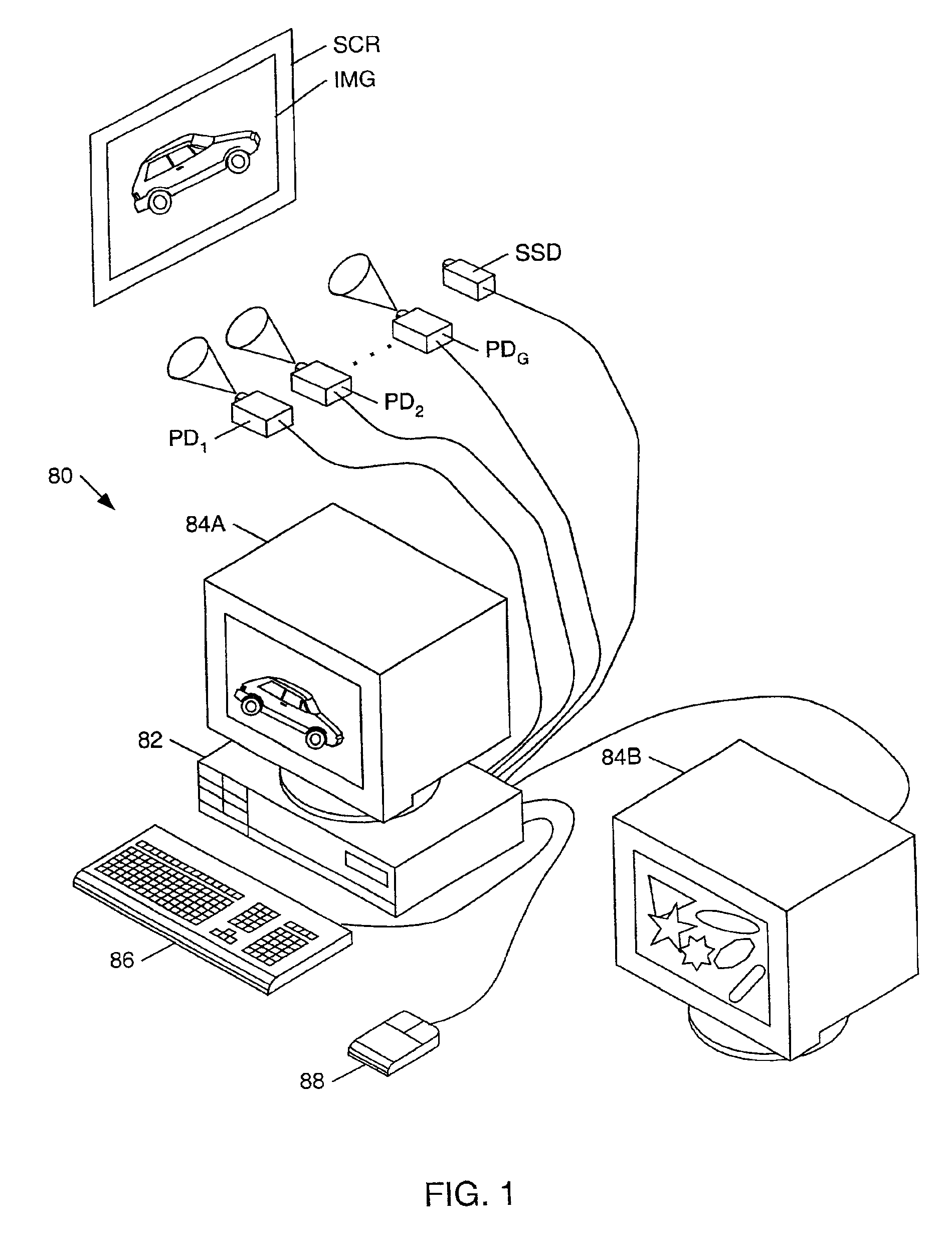
[0058]FIG. 1 illustrates one embodiment of a computer system 80 which performs three-dimensional (3-D) and / or two-dimensional (2D) graphics according to the present invention. Computer system 80 comprises a system unit 82 which may couple to display devices such as monitors 84A and 84B and / or projection devices P1 through PDG. The display devices may be realized by any of a variety of display technologies. For example, the projection devices PD1 through PDG may be CRT-based projectors, LCD projectors, gas-plasma projectors, digital micromirror projectors, liquid crystal on silicon (LCOS) projectors, etc., or any combination thereof. System unit 82 may couple to an arbitrary number of display devices.

[0059]System unit 82 may also couple to various input devices such as a keyboard 86, a mouse 88, a spectrum sensing device SSD (e.g. a spectrophotometer), a video camera, a trackball, a digitizing tablet, a six-degree of freedom input device, a head tracker, an eye tracker, a data glove,...


PUM


Abstract

A system and method for performing color correction based on physical measurements (or estimations) of color component spectra (e.g. red, green, blue color component spectra). A color correction system may comprise a spectrum sensing device, a color calibration processor, and a calculation unit. The spectrum sensing device may be configured to measure color component power spectra for pixels generated by one or more display devices on a display surface. The color calibration processor may receive power spectra for a given pixel from the spectrum sensing device and compute a set of transformation parameters in response to the power spectra. The transformation parameters characterize a color correction transformation for the given pixel. The color calibration processor may compute such a transformation parameter set for selected pixels in the pixel array. The calculation unit may be configured to (a) compute initial color values for an arbitrary pixel in the pixel array, (b) compute modified color values in response to the initial color values and one or more of the transformation parameter sets corresponding to one or more of the selected pixels, and (d) transmit the modified color values to the display device.

Description

CROSS REFERENCE TO RELATED APPLICATIONS[0001]This application claims the benefit of priority to U.S. Provisional Application No. 60 / 242,640 filed on Oct. 23, 2000 entitled “MULTI-SPECTRAL COLOR CORRECTION”.BACKGROUND OF THE INVENTION[0002]1. Field of the Invention[0003]This invention relates generally to the field of computer graphics and, more particularly, to a system and method for correcting the presentation of color by one or more display devices (e.g. projection devices).[0004]2. Description of the Related Art[0005]A light beam may be described as a superposition of beams having a continuum of wavelengths. The amount of power concentrated at each wavelength λ of the continuum is given by a function F(λ) known as the power spectrum. The power spectrum may be measured by a spectrum sensing device such as a spectroradiometer. The power spectrum determines the perceived color of the light beam for a given observer. The space of possible power spectra is infinite dimensional. Howev...

Claims


Application Information

Patent Timeline
IPC IPC(8): G09G5/395G06F3/14G09G5/36G09G1/28H04N9/73G09G5/393
CPCG06F3/1431G09G1/285G09G5/395H04N9/73G06F3/1446G09G5/393G09G2320/0285
Inventor DEERING, MICHAEL F.
Owner ORACLE INT CORP
Learn More