
Computer implemented method and system for transmitting graphical images from server to client at user selectable resolution

a computer and server technology, applied in the field of graphical images, can solve the problems of insufficient bandwidth, insufficient bandwidth, and insufficient bandwidth to down-load graphical image files to users' computers, etc., and achieve the effect of reducing the average time it takes to down-load a graphical image file to a user's computer, and reducing the cost of the system

Inactive Publication Date: 2005-09-27
RAKUTEN INC
View PDF35 Cites 42 Cited by
  • Summary
  • Abstract
  • Description
  • Claims
  • Application Information

AI Technical Summary

Benefits of technology

[0018]The advantages of the invention are numerous. One advantage of the invention is that graphical images can be transmitted over a network with a reduced amount so as to conserve precious network bandwidth, improve transmission time, and to reduce loads placed on server machines. Another advantage is that a user has a choice as to the amount of a graphical image file needed depending on an intended use for the image. For the images are simply being displayed in a small one inch by one inch arrangement, then only a small amount of the graphical image file need be transmitted. On the other hand, if the image is to be printed with high quality at a page-size, then a substantially larger amount of the graphical image file needs be transmitted (but this is typically still less than the complete graphical image file). In either case, less data is transmitted so less bandwidth is required and transmission time is improved. Further, in the case where the image is to be printed with picture quality on a large format, then a large amount (perhaps all) of data would be transmitted, which is very likely more data than would be conventionally available. The format of the data can also vary with the intended use (e.g., display format, printer formats, storage formats, etc.). Another advantage of the invention is that an author of an image need only store the associated graphical image file once in a high quality format, thereafter, the invention operates via a negotiation process between client and server, to meter down the amount of the graphical image file as is warranted. Yet another advantage of the invention is that moves with technology in that as transmission bandwidth becomes greater or transmission rates become faster, the previously stored image files are automatically useable without changes.

Problems solved by technology

One major problem, however, with down-loading graphical image files from the Internet is bandwidth constraints.
The bandwidth constraints are primarily due to how user's computers connect to the Internet.
Hence, the average time it takes to down-load a graphical image file to a user's computer is unduly long.
Thus, the communication links by which user's computers connect to the Internet are the transmission bottleneck.
However, the reduction in size provided by compression does lead to distortion.
Although a limited amount of compression is acceptable, there is a limit as to the compression rate that still produces acceptable quality.
The amount of compression achieved by existing compression techniques does not provide both high quality and rapid transmission over modem connections.
Consequently, compression helps with the bandwidth constraints or transmission bottleneck, but does not sufficiently solve the problem.
The transmission of graphical image files in networks within companies (internet) face similar problems.
While some users may have high speed connections to servers on the internet, other users have much slower modem connections.
However, both types of users need to obtain graphical image files with acceptable response times. Hence, in the internet case, the communication links by which user's computers connect to the internet are also the transmission bottleneck.

Method used


Image

  • Computer implemented method and system for transmitting graphical images from server to client at user selectable resolution
  • Computer implemented method and system for transmitting graphical images from server to client at user selectable resolution
  • Computer implemented method and system for transmitting graphical images from server to client at user selectable resolution

Examples


Embodiment Construction

[0036]Embodiments of the invention are discussed below with reference to the drawings. However, those skilled in the art will readily appreciate that the detailed description given herein with respect to these figures is for explanatory purposes as the invention extends beyond these limited embodiments.

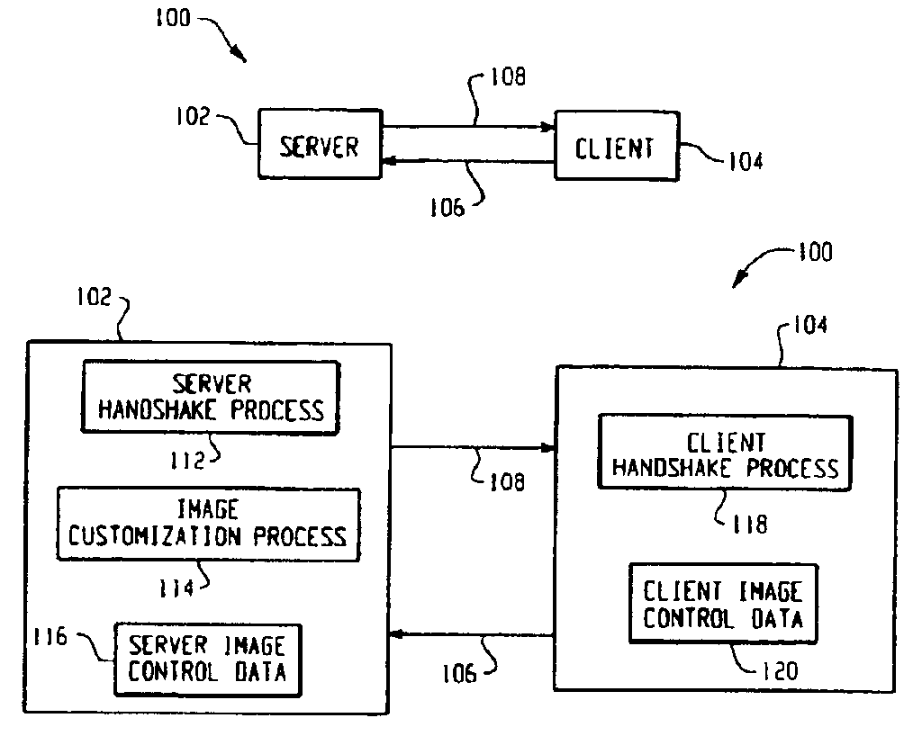
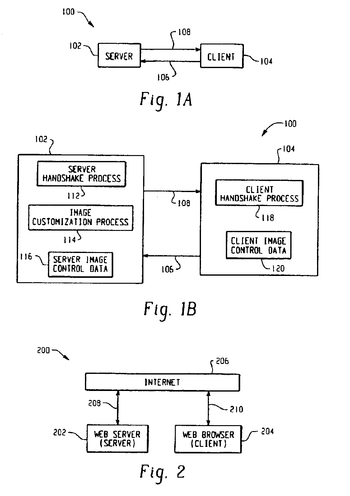
[0037]FIG. 1A is a basic block diagram of a communications system 100 according to an embodiment of the invention. The communications system 100 includes a server 102 and a client 104. Images are stored on the server 102 and each image typically has a predetermined physical size and resolution that lead to a total image size. Each such image is stored on the server 102 as an image file. The client 104 sends a request for an image over a link 106 to the server 102. The server 102 then in turn sends an appropriate amount of data for the corresponding image file to the client 104 over a link 108.

[0038]FIG. 1B is a detailed block diagram of the communications system 100 illustrated in FIG...


PUM


Abstract

Techniques for transmitting graphical images in a network environment are described. According to the techniques, the amount of data of the graphical images that is transmited is customized in accordance with client and / or server supplied information. The techniques enable graphical images to be transmitted more efficiently than previously possible, thus saving precious network bandwidth and reducing transmision time. The invention is particularly suitable for network (Internet or Internet) implementations wherein graphical images often need transferred.

Description

CROSS REFERENCE TO RELATED APPLICATIONS[0001]This application is a continuation of U.S. application Ser. No. 09 / 036,268, filed Mar. 6, 1998 now U.S. Pat. No. 6,501,472 which is a continuation of U.S. application Ser. No. 08 / 622,528 filed Mar. 25, 1996, now U.S. Pat. No. 5,764,235.BACKGROUND OF INVENTION[0002]1. Field of the Invention[0003]The present invention relates to graphical images and, more particularly, to the transmission of graphical images.[0004]2. Description of the Related Art[0005]To meet the multimedia revolution, computers have become more powerful and have provided more multimedia support. In particular, graphic capabilities of personal computers have been greatly enhanced in recent years due to technological improvements in peripheral devices and software products. Input peripheral devices, such as scanners and CD-ROM players, enable personal computers to obtain graphical image files. Software products can also be used to create graphical images using paint or draw...

Claims


Application Information

Patent Timeline
Patent Type & Authority Patents(United States)
IPC IPC(8): H04L12/56H04L29/06H04L29/08G06F17/22G06F17/30
CPCG06F17/2258G06F17/30905H04L29/06H04L47/10H04L65/4084H04L65/602H04L69/04H04L67/2828H04L67/02H04L29/06027H04L67/42H04L67/2823H04L69/24H04L69/329G06F16/9577G06F40/149H04L65/762H04L65/612H04L67/5651H04L67/565H04L9/40H04L65/1101H04L67/01
Inventor HUNT, WILLIAM J.NEIL, EDWARD JAMESHABER, STEVEN F.WOOD, RUSSELL D.
Owner RAKUTEN INC
Learn More