
Multiple-element antenna

a multi-element, antenna technology, applied in the direction of elongated active element feed, resonant antenna, independent non-interacting antenna combination, etc., can solve the problems of poor communication signal radiation and reception in many environments, and unsatisfactory sar levels

Inactive Publication Date: 2005-09-27
MALIKIE INNOVATIONS LTD
View PDF98 Cites 51 Cited by
  • Summary
  • Abstract
  • Description
  • Claims
  • Application Information

AI Technical Summary

Benefits of technology

The patent describes a multiple-element antenna that includes a monopole portion and a dipole portion. The monopole portion has a recess between the top and bottom sections, and the bottom section includes a monopole feeding port. The dipole portion has at least one dipole feeding port. The dipole portion is positioned within the recess defined by the monopole portion to electromagnetically couple them. The technical effect of this design is that it allows for improved communication between the mobile communication device and the antenna.

Problems solved by technology

Many known embedded antenna structures such as the inverted F antenna, however, still exhibit undesirably high SAR levels, and may also provide poor communication signal radiation and reception in many environments.

Method used


Image

  • Multiple-element antenna
  • Multiple-element antenna
  • Multiple-element antenna

Examples


Embodiment Construction

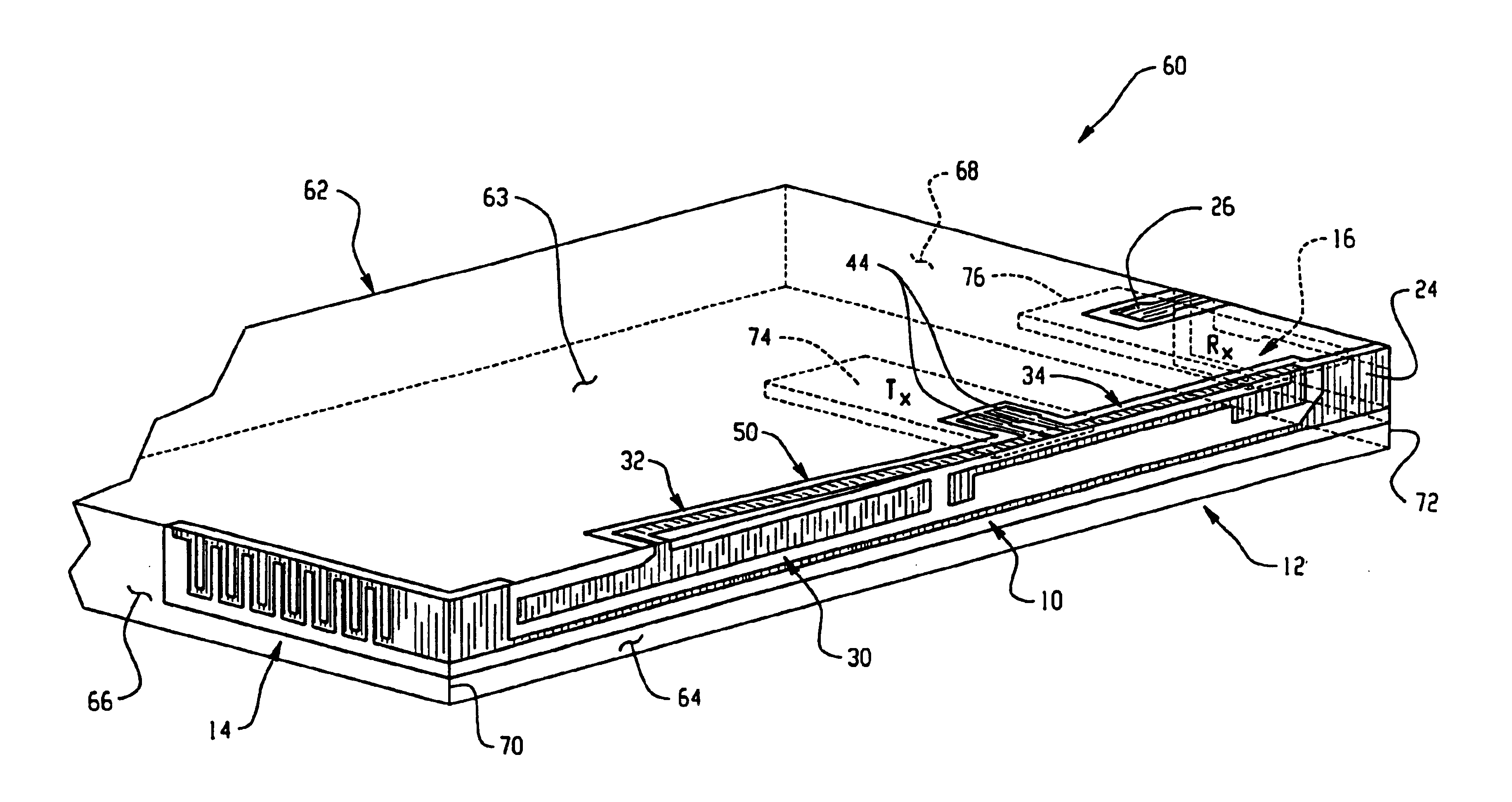
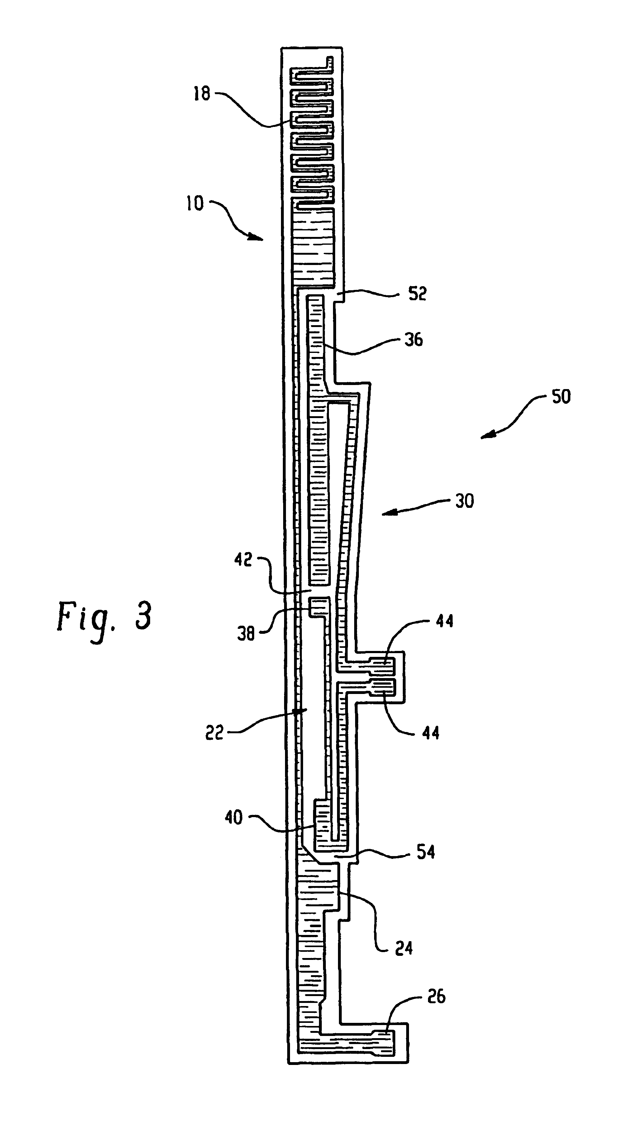
[0010]Referring now to the drawing figures, FIGS. 1-3 show an exemplary multiple-element antenna 50. FIG. 1 is an illustration of a monopole portion 10 of the multiple-element antenna 50, FIG. 2 illustrates a dipole portion 30 of the multiple-element antenna 50, and FIG. 3 shows the multiple-element antenna 50 with both its monopole 10 and dipole 30 portions.

[0011]Operationally, the monopole 10 and dipole 30 portions of the antenna 50 may each be tuned to a different frequency band, thus enabling the multiple-element antenna 50 to function as the antenna in a dual-band mobile communication device. For example, the multiple-element antenna 50 may be adapted for operation at the General Packet Radio Service (GPRS) frequency bands of 900 Mhz and 1800 Mhz, the Code Division Multiple Access (CDMA) frequency bands of 800 Mhz and 1900 Mhz, or some other pair of frequency bands.

[0012]With reference to FIG. 1, the monopole portion 10 of the antenna 50 includes a middle section 12, a top sect...


PUM


Abstract

A multiple-element antenna is provided that includes a monopole portion and a dipole portion. The monopole portion has a top section, a middle section, and a bottom section. The middle section defines a recess between the top and bottom sections, and the bottom section includes a monopole feeding port configured to couple the monopole portion of the multiple-element antenna to communications circuitry in a mobile communication device. The dipole portion has at least one dipole feeding port configured to couple the dipole portion of the multiple-element antenna to communications circuitry in the mobile communications device. The dipole portion of the multiple-element antenna is positioned within the recess defined by the monopole portion of the multiple-element antenna in order to electromagnetically couple the monopole portion with the dipole portion.

Description

CROSS-REFERENCE TO RELATED APPLICATION[0001]This application claims priority as a continuation of U.S. patent application Ser. No. 10 / 119,079 filed Apr. 9, 2002, now U.S. Pat. No. 6,664,930. U.S. patent application Ser. No. 10 / 119,079 claims priority from and is related to the following prior application: A Multiple-Element Antenna For A Mobile Communication Device, U.S. Provisional Application No. 60 / 283,311, filed Apr. 12, 2001. These prior applications, including the entire written descriptions and drawing figures, are hereby incorporated into the present application by reference.FIELD OF THE INVENTION[0002]This invention relates generally to the field of multi-feed antennas. More specifically, a multiple-element antenna is provided that is particularly well-suited for use in Personal Digital Assistants, cellular telephones, and wireless two-way email communication devices (collectively referred to herein as “mobile communication devices”).BACKGROUND OF THE INVENTION[0003]Mobile ...

Claims


Application Information

Patent Timeline
Patent Type & Authority Patents(United States)
IPC IPC(8): H01Q5/00H01Q1/38H01Q9/04H01Q9/28H01Q9/40H01Q21/28H01Q21/00H01Q5/40H04B1/00H04B1/40
CPCH01Q1/38H01Q9/28H01Q5/40H01Q21/28H01Q9/40
Inventor WEN, GEYIQI, YIHONGBANDURSKA, KRYSTYNAJARMUSZEWSKI, PERRY
Owner MALIKIE INNOVATIONS LTD
Learn More