
Apparatus and method for generating electrical current from the nuclear decay process of a radioactive material

a nuclear decay and apparatus technology, applied in the direction of electric generator control, instruments, nuclear engineering, etc., can solve the problems of inability to achieve much greater than ten percent energy conversion rate, inability to stabilize and continue to decay, and inefficiency of the energy conversion process

Inactive Publication Date: 2005-09-27
JOYRRAL
View PDF31 Cites 23 Cited by
  • Summary
  • Abstract
  • Description
  • Claims
  • Application Information

AI Technical Summary

Benefits of technology

[0012]An apparatus for generating electrical current from a nuclear decay process of a radioactive material is disclosed, the apparatus comprising: an enclosed volume of radioactive material; and a junction region disposed within said enclosed volume, wherein a first portion of said junction region is disposed at a declination angle of greater than about 55° relative to a second po...

Problems solved by technology

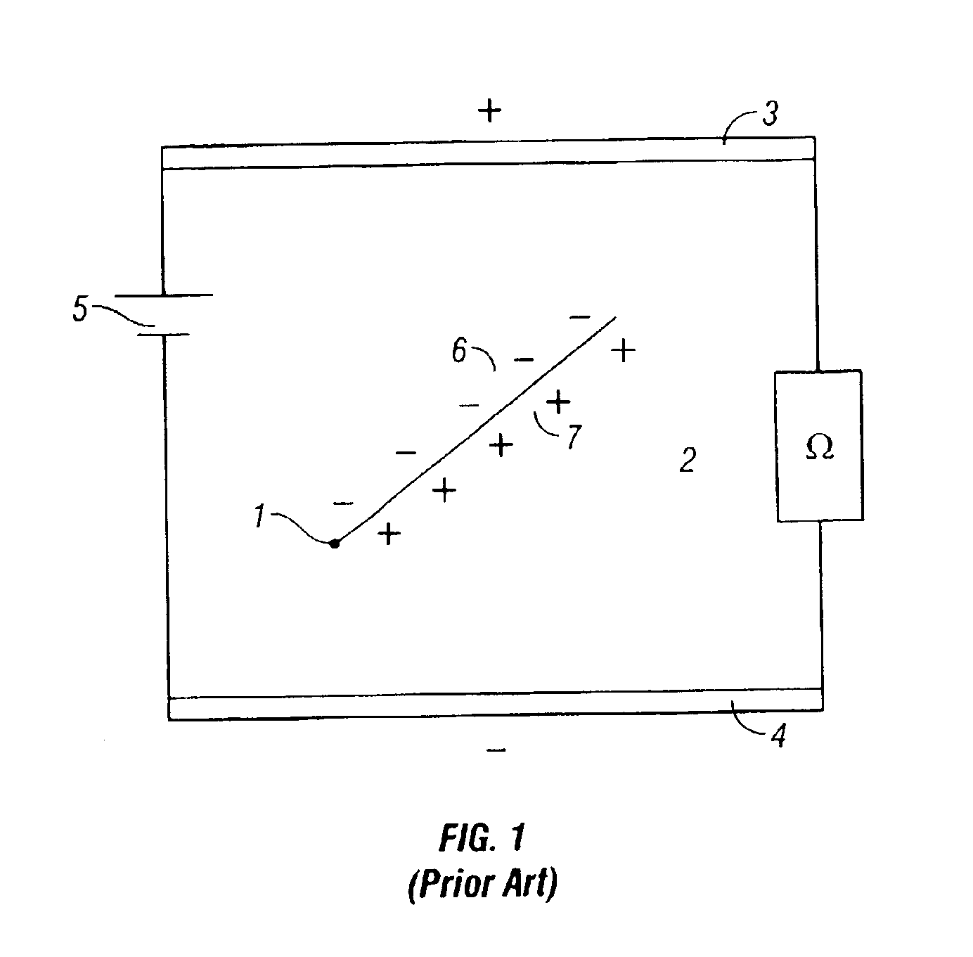
This decay process alters the total atomic mass of the parent nucleus, and produces a daughter nucleus, having a reduced mass, that may also be unstable and continue to decay.
Previously, a major drawback when attempting to use energy derived from a nuclear decay series to power devices in remote locations has been an inefficiency of the energy conversion process.
For example, it has proven difficult to achieve much greater than a ten percent energy conversion rate, especially when the energy is transferred via a thermodynamic cycle as described above.
None of these nuclear batteries have been developed commercially for practical applications.

Method used


Image

  • Apparatus and method for generating electrical current from the nuclear decay process of a radioactive material
  • Apparatus and method for generating electrical current from the nuclear decay process of a radioactive material
  • Apparatus and method for generating electrical current from the nuclear decay process of a radioactive material

Examples


Embodiment Construction

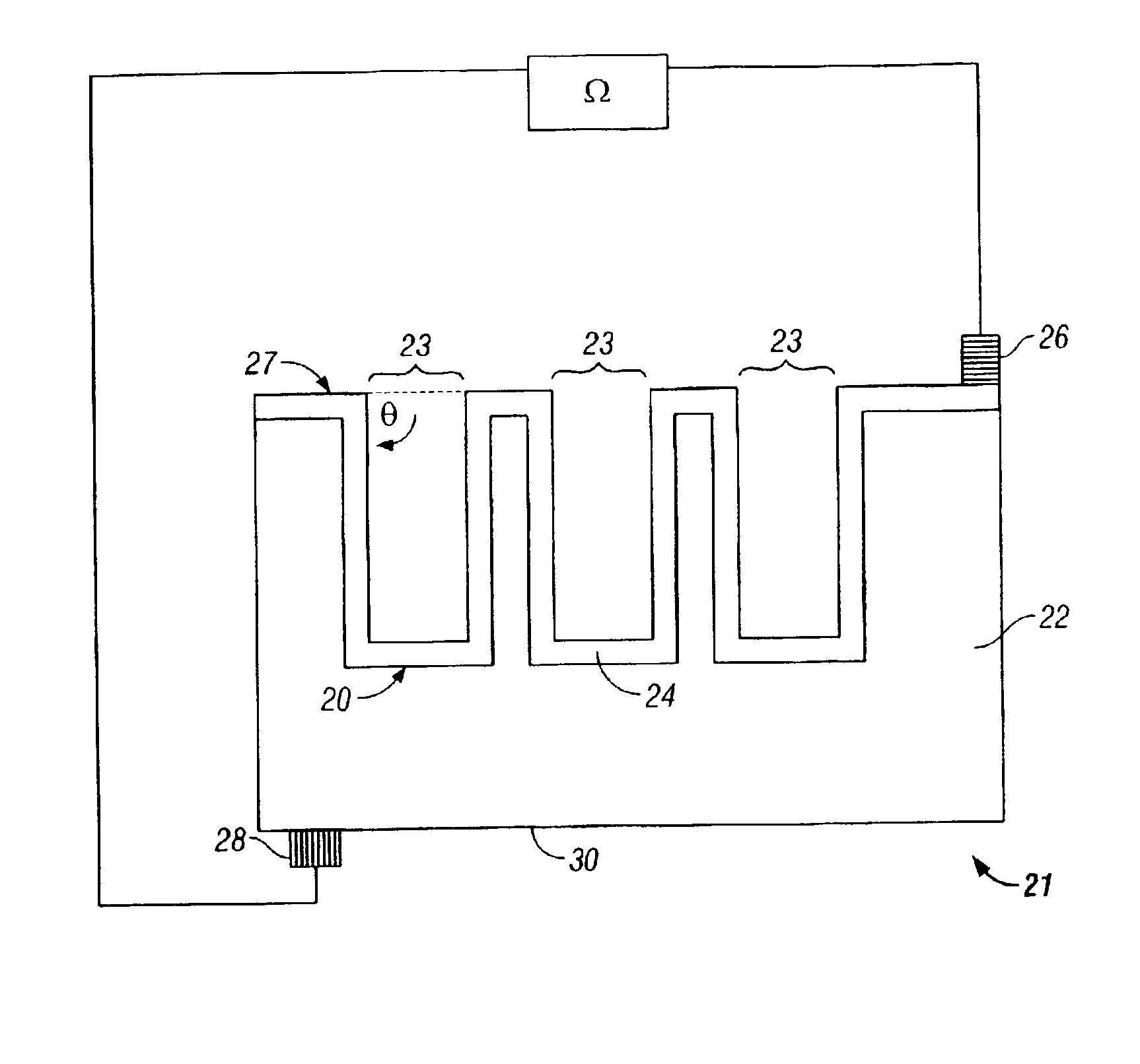
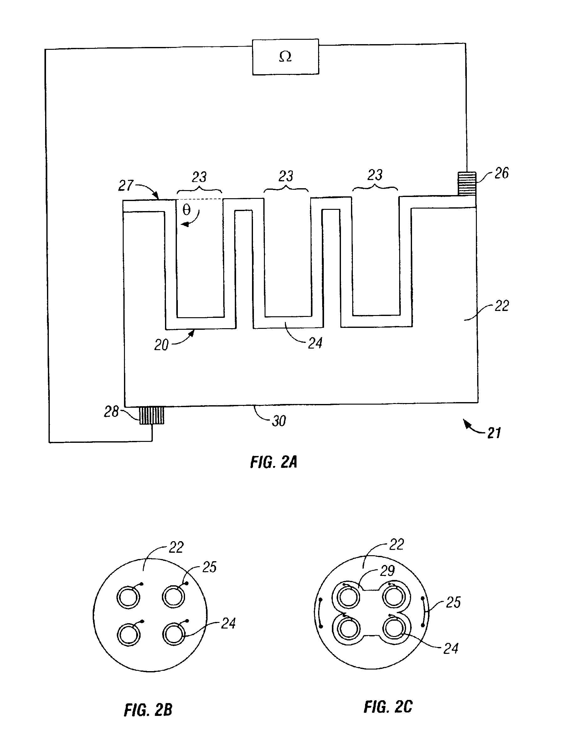
[0020]Referring now to FIG. 2A, an example embodiment is seen in which a silicon wafer 21 has been doped to provide a p-type region 22, an n-type region 24 and a junction region 20. Contact 28 connects p-type region 22 to a first side of a load Ω via a low-resistivity contact region 30 (e.g., a metal, for example, aluminum). A second low-resistivity contact surface region disposed between contact surface region 27 and contact 26 (e.g., a metal deposit, for example, gold) permits a current transport means for charges liberated by energetic decay electron energy absorption in n-type region 24 to reach contact 26 such that n-type region 24 is in electrical communication with another side of load Ω. Tritium gas (not shown), which is disposed in deep pores 23, decays. Each decay event generates an energetic beta particle (not shown) that enters n-type region 24, where an electric field exists relative to junction region 20 and contact surface region 27 caused by the contact potential bet...


PUM


Abstract

An apparatus and method for generating electrical power from the decay process of a radioactive material is disclosed, wherein a volume of radioactive material and a junction region are enclosed in a cell. The junction region is formed by appropriate construction of a number of p-type and n-type dopant sites. At least a portion of one of the junction regions is disposed within a porous region having an aspect ratio of greater than about 20:1, and disposed at an angle of greater than about 55° measured relative to the surface area in which it is formed. The dimensions and shapes of the macroporous regions and the improved junction region surface area available for collecting charged particles emitted during a radioactive decay series permit an improved current to be derived from the apparatus than would otherwise be expected given its external dimensions.

Description

CROSS-REFERENCE TO RELATED APPLICATIONS[0001]The instant application is a continuation-in-part of prior U.S. application Ser. No. 10 / 356,411, filed Jan. 31, 2003, now issued as U.S. Pat. No. 6,774,531.BACKGROUND[0002]The present invention relates generally to an apparatus for generating electrical current from the nuclear decay process of a radioactive material. In a specific, non-limiting example, the invention relates to an energy cell (e.g., a battery) for generating electrical current derived from particle emissions occurring within a confined volume of radioactive material (e.g., tritium gas).[0003]Radioactive materials randomly emit charged particles from their atomic nuclei. Examples are alpha particles (i.e., 4He nuclei) and beta particles (i.e., either electrons or positrons). This decay process alters the total atomic mass of the parent nucleus, and produces a daughter nucleus, having a reduced mass, that may also be unstable and continue to decay. In such a nuclear decay ...

Claims


Application Information

Patent Timeline
IPC IPC(8): G21H1/00H01L31/04H01M14/00H02P9/04G21FG21H1/06
CPCG21H1/06
Inventor GADEKEN, LARRY
Owner JOYRRAL
Learn More