Method of making an intraluminal stent graft
a technology of intraluminal stents and grafts, which is applied in the field of making thin wall intraluminal grafts, can solve the problems of limited thinness of the wall, limited ability of the tube to be contracted into a small cross-sectional area, and occasional mortality
- Summary
- Abstract
- Description
- Claims
- Application Information
AI Technical Summary
Benefits of technology
Problems solved by technology
Method used
Image
Examples
example 1
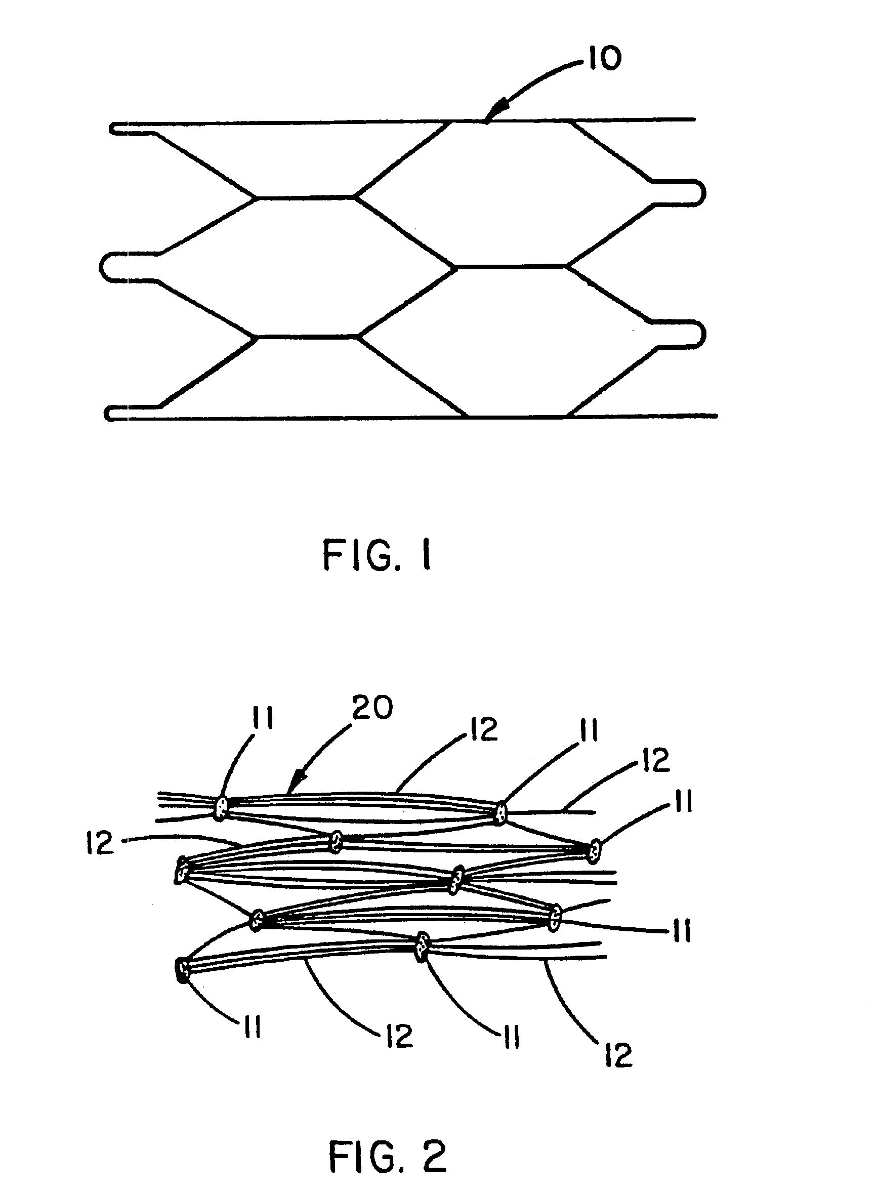
[0030]A Nitinol wire stent 10 (Nitinol Medical Technologies, Boston, Mass.) of the type described by FIG. 1 was provided with both a luminal covering and an exterior covering of expanded PTFE film. This 3 cm long stent was formed from 0.25 mm diameter Nitinol wire into a tubular shape of interlocking hexagons. The luminal and exterior coverings were both made from a uniaxially-oriented film having fibrils oriented substantially in a single direction wherein the fibrils were all substantially parallel to each other. The luminal covering was provided with the fibrils oriented parallel to the longitudinal axis of the tubular stent; the exterior covering was provided with the fibrils oriented substantially circumferential to the tubular stent. The film used for both the luminal and exterior coverings was a porous expanded PTFE film having a discontinuous, porous coating of FEP applied to one side of the porous expanded PTFE film. Examination of the FEP coated side of the film by scannin...
example 2
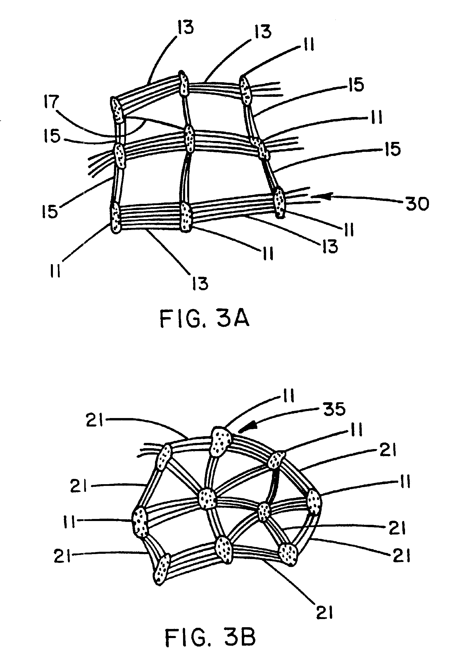
[0041]A Nitinol wire stent of the same type used for Example 1 was provided with a luminal covering of a porous expanded PTFE film having a microstructure of biaxially-oriented fibrils as shown by FIG. 3A. This was accomplished by wrapping a hollow tubular mandrel of non-porous PTFE with a layer of porous expanded PTFE film having a continuous (nonporous) coating of FEP with the FEP-coated side of the film facing outwardly away from the mandrel surface. This film was about 0.02 mm thick; the porous expanded PTFE had a microstructure of uniaxially-oriented fibrils with the fibrils oriented circumferentially about the exterior surface of the mandrel. The Nitinol stent was carefully fitted over the film-wrapped portion of the mandrel. The mandrel assembly was then placed into an oven set at 360° C. for four minutes. After removal from the oven and subsequent cooling, the mandrel was removed from the stent leaving the wrapped film adhered to the luminal surface of the stent. This film w...
example 3
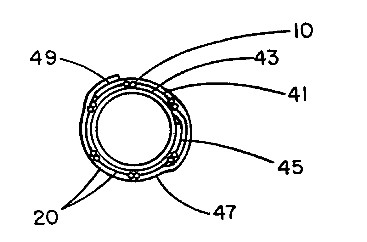
[0045]A Palmaz stent of the balloon-expandable type (part no. PS30, Johnson & Johnson Interventional Systems, Inc., Warren, N.J.) was adjusted from its collapsed outside diameter of 3.4 mm to an enlarged outside diameter of 8.0 mm by inserting a tapered stainless steel mandrel followed by a straight 8.0 mm diameter stainless steel mandrel. This stent was then provided with a single layer exterior wrapping of the same discontinuously FEP-coated, porous expanded PTFE coating used for the exterior wrapping of the stent of Example 1. This was accomplished by wrapping the film about the exterior surface of the mandrel with the uniaxially-oriented fibrils of the film microstructure oriented parallel to the longitudinal axis of the stent. This exterior covering 61 is described by the transverse cross section of FIG. 6. A 2 mm wide seam 45 was formed from the overlapped edges of the porous expanded PTFE film 20 by temporarily placing a thin sheet of polyamide film over these edges and apply...
PUM
 Abstract
Description
Claims
Application Information
 - R&D
- Intellectual Property
- Life Sciences
- Materials
- Tech Scout
- Unparalleled Data Quality
- Higher Quality Content
- 60% Fewer Hallucinations
Browse by: Latest US Patents, China's latest patents, Technical Efficacy Thesaurus, Application Domain, Technology Topic, Popular Technical Reports.
© 2025 PatSnap. All rights reserved.Legal|Privacy policy|Modern Slavery Act Transparency Statement|Sitemap|About US| Contact US: help@patsnap.com


