
Regionally time multiplexed emulation system

a time multiplexing and emulation system technology, applied in the field of emulation systems, can solve the problems of not supporting time multiplexing of asynchronous signals for emulating asynchronous logic, synchronizing clock signals in the emulation system, and increasing the number of routing chips required to provide adequate flexibility to concurrently route large numbers of input and output signals to and from the fpga

Inactive Publication Date: 2005-09-20
MENTOR GRAPHICS HLDG +1
View PDF17 Cites 17 Cited by
  • Summary
  • Abstract
  • Description
  • Claims
  • Application Information

AI Technical Summary

Problems solved by technology

However, given the large number of FPGAs which may be included in an emulation system, the number of routing chips required to provide adequate flexibility to concurrently route large numbers of input and output signals to and from an FPGA has become prohibitively expensive.
One problem with the Babb et al. system is that it is primarily designed to emulate synchronous logic providing synchronous signals, and does not support time multiplexing of asynchronous signals for emulating asynchronous logic.
Additionally, even with the use of time multiplexing, or in systems where asynchronous signals are hard-wired to dedicated inputs and outputs, other problems still exist.
One such problem is that of synchronizing clock signals in the emulation system.
Despite the use of time multiplexing to reduce overall system size, the system can still remain relatively large.
Synchronizing high frequency clock signals across such a large area creates a significant problem.

Method used


Image

  • Regionally time multiplexed emulation system
  • Regionally time multiplexed emulation system
  • Regionally time multiplexed emulation system

Examples


Embodiment Construction

[0023]In the following description, for purposes of explanation, specific numbers, materials and configurations are set forth in order to provide a thorough understanding of the present invention. However, it will be apparent to one skilled in the art that the present invention may be practiced without the specific details. In other instances, well known features are omitted or simplified in order not to obscure the present invention.

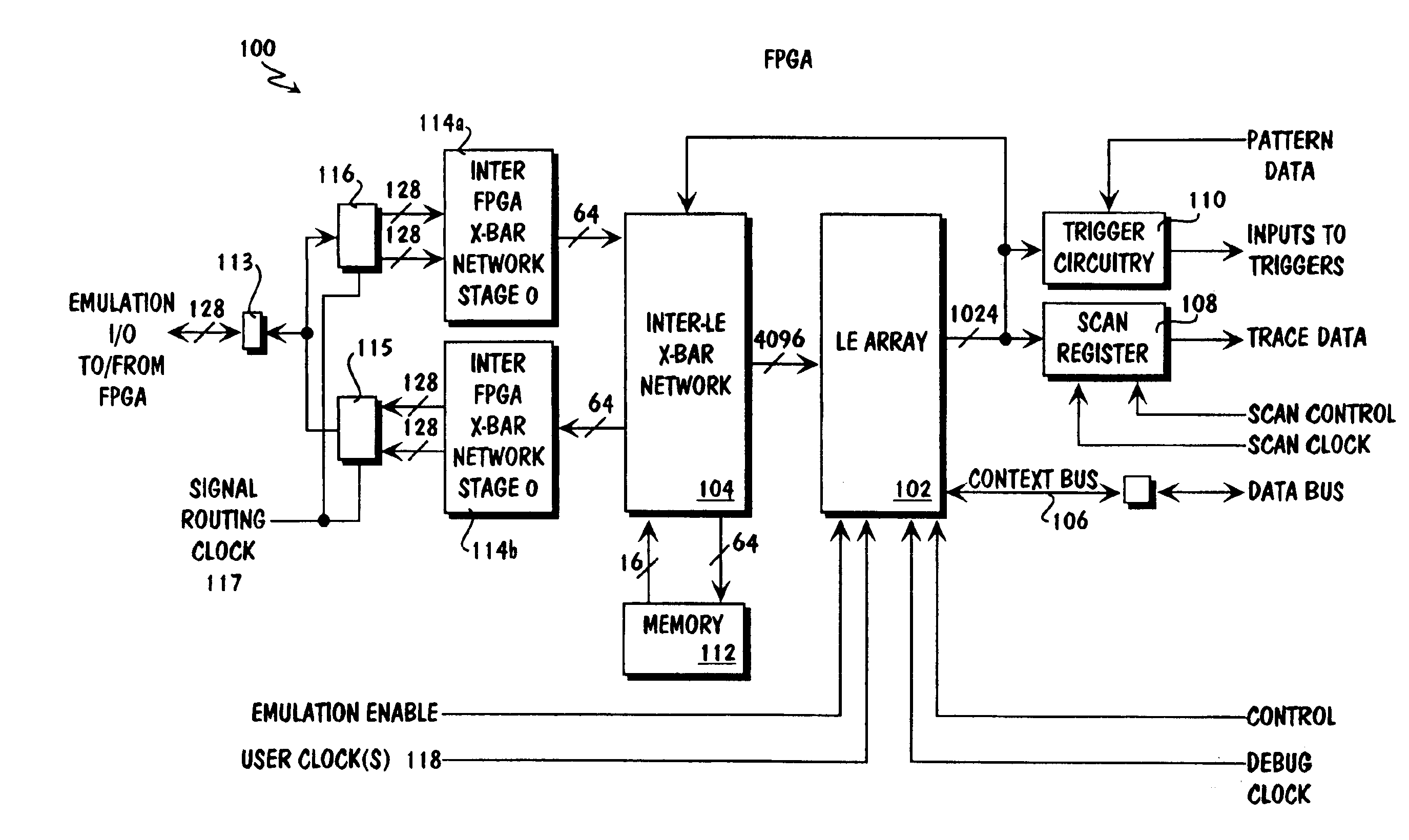
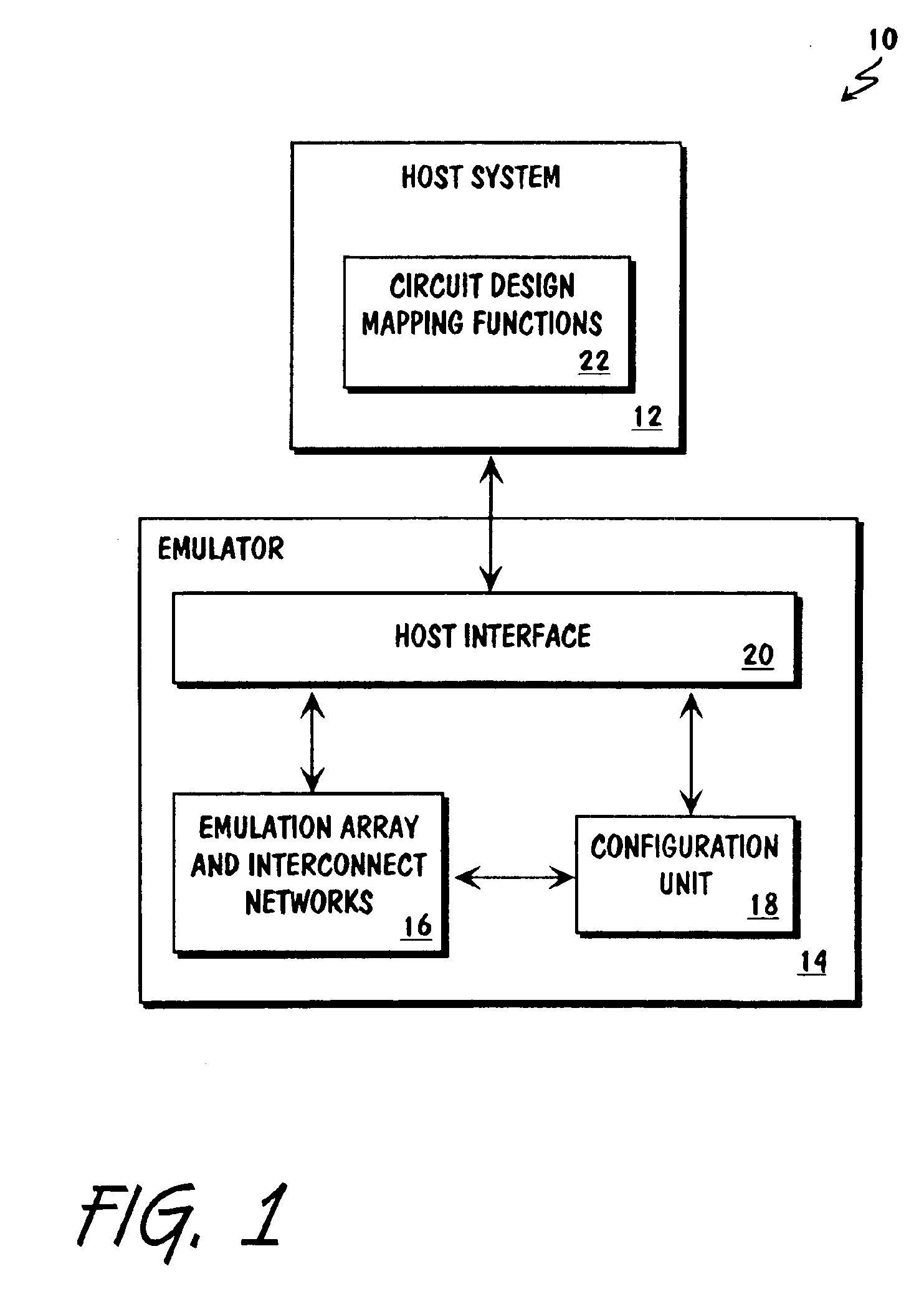
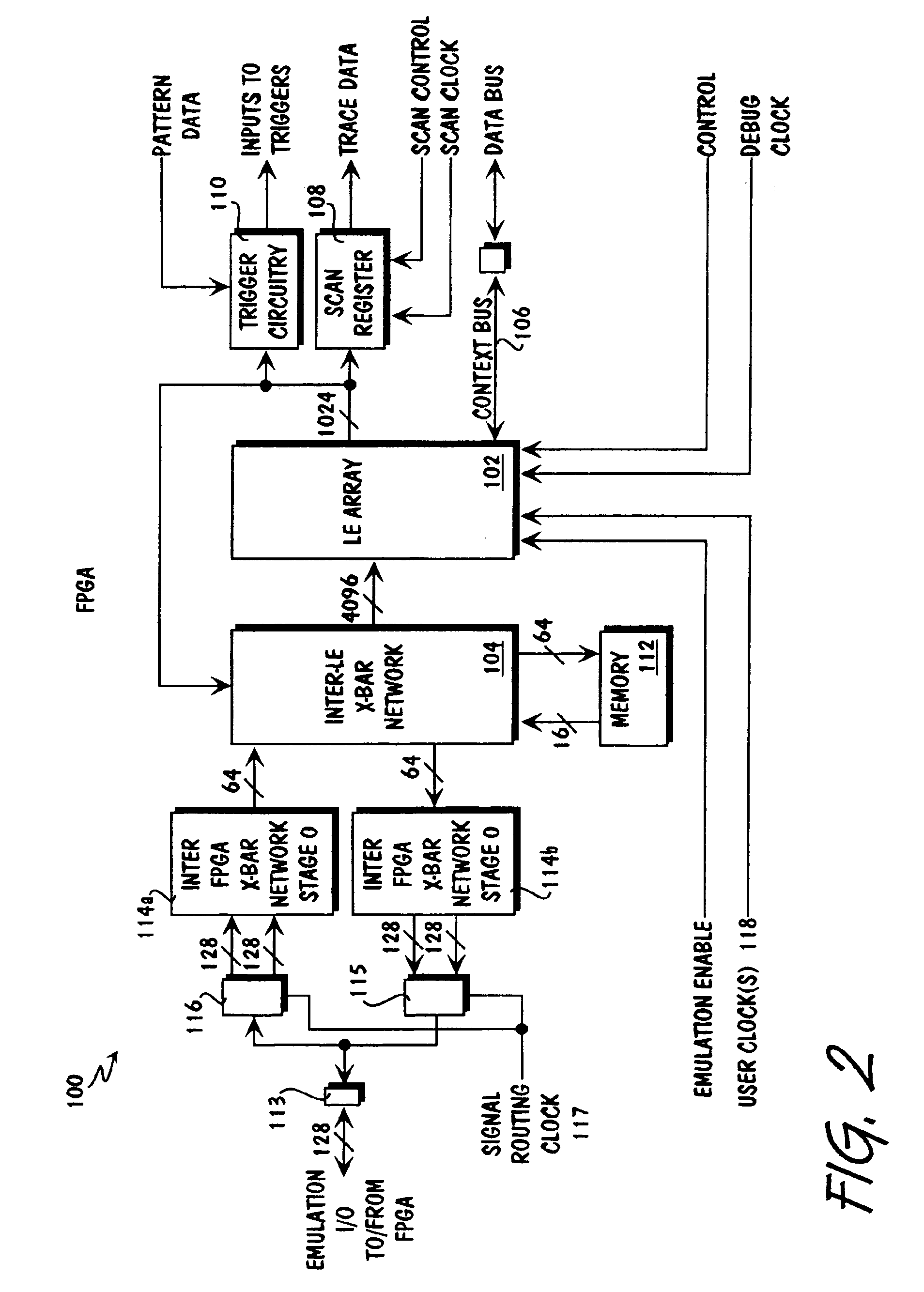
[0024]FIG. 1 is a block diagram showing an exemplary emulation system which incorporates the teachings of the present invention. As illustrated, an emulation system 10 includes host system 12 and emulator 14. Host system 12 includes in particular circuit design mapping functions 22 incorporated with the teachings of the present invention. In one embodiment, circuit design mapping functions 22 are implemented in software. In this embodiment, circuit design mapping software 22 is stored in a suitable storage medium (not shown) of host system 12, and is lo...


PUM


Abstract

A regionally time multiplexed emulation system includes an emulator for emulating a circuit design. The emulator includes a plurality of reconfigurable logic devices with buffered I / O pins and reconfigurable logic elements. The reconfigurable logic devices are reconfigurable to emulate a circuit design using at least one user clock to clock the logic elements and at least one signal routing clock to time multiplex the routing of emulation signals between the reconfigurable logic devices, with the at least one signal routing clock being independent of the at least one user clock.

Description

BACKGROUND OF THE INVENTION[0001]1. Field of the Invention[0002]The present invention relates to the field of emulation systems. More specifically, the present invention relates to methodology for increasing capacity of an emulation system.[0003]2. Background Information[0004]Emulation systems for emulating circuit designs are known in the art. Typically, prior art emulation systems are formed using conventional general purpose field programmable gate arrays (FPGAs) and general purpose routing chips. A circuit design to be emulated is “realized” on the emulation system by compiling a “formal” description of the circuit design, and mapping the circuit design onto the logic elements (LEs) of the FPGAs and the routing chips.[0005]As circuit designs have become larger and larger, up to and including designs having millions of transistors, a similar increase in size of emulation systems has become necessary in order to emulate such circuit designs. Large emulation systems typically inclu...

Claims


Application Information

Patent Timeline
IPC IPC(8): G06F17/50G06F11/22H01L21/82H03K19/173
CPCG06F17/5027G06F30/331
Inventor REBLEWSKI, FREDERICLEPAPS, OLIVIERBARBIER, JEAN
Owner MENTOR GRAPHICS HLDG
Learn More