
Least mean power consumption in telecommunications systems

a technology of telecommunications systems and power consumption, applied in the field of telecommunication networks, can solve the problems of waste of power, typical telephones use much more power off-hook than on-hook,

Inactive Publication Date: 2005-09-20
ARRIS ENTERPRISES LLC
View PDF4 Cites 31 Cited by
  • Summary
  • Abstract
  • Description
  • Claims
  • Application Information

AI Technical Summary

Benefits of technology

The present invention relates to telecommunications networks and more particularly to dynamic power adjustment in telecommunications networks. The invention aims to minimize wasted power by managing the power provided to connected customer equipment. The invention provides a programmable access point that interfaces with a network and customer premise equipment, allowing for dynamic adjustment of power levels based on the needs of the connected equipment. The invention also includes an operating limits test to ensure that the programmable access point operates within safe limits. Overall, the invention allows for efficient management of power in telecommunications networks.

Problems solved by technology

Further, a typical telephone uses much more power off-hook than on-hook.
However, when only a single phone is off-hook, that same access point is providing much more power than is necessary, all of which is wasted.

Method used


Image

  • Least mean power consumption in telecommunications systems
  • Least mean power consumption in telecommunications systems
  • Least mean power consumption in telecommunications systems

Examples


Embodiment Construction

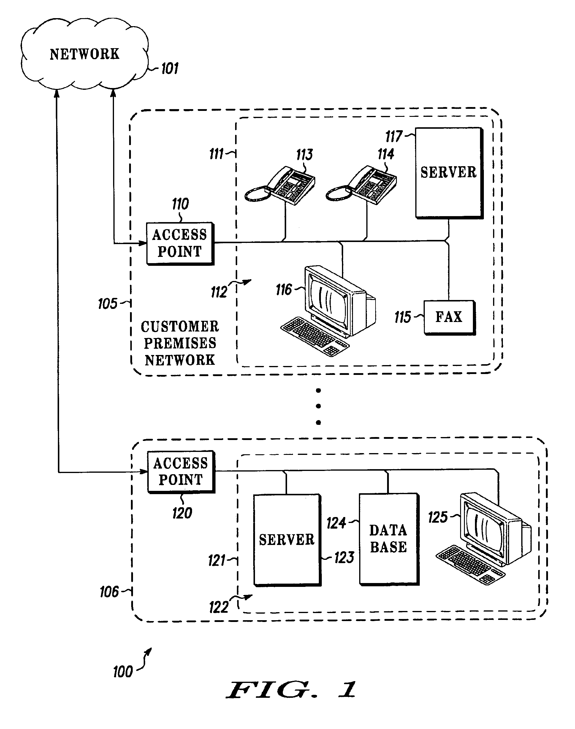
[0012]Turning now to the drawings and more particularly FIG. 1, a general communications network 100 is shown, such as a telephone network.

[0013]Network 101 is coupled to an access point 110 within a customer premises network 105. The access point 110 is coupled to customer premise equipment 112 which consists of telephones 113 and 114, a fax machine 115, a computer terminal 116, and a server 117. The customer premise equipment 112 is shown located in customer premises 111 such as a residence, a suite, a building, or group of buildings as in a campus. Network 101 is further coupled to an access point 120 within another customer premises network 106. Access point 120 is coupled to customer premise equipment 122 which consists of a server 123, a database 124, and a workstation 125. Customer premise equipment 122 is shown located in customer premises 121. It is understood that network 101 can be connected to further access points as indicated by the ellipsis shown in FIG. 1.

[0014]Custo...


PUM


Abstract

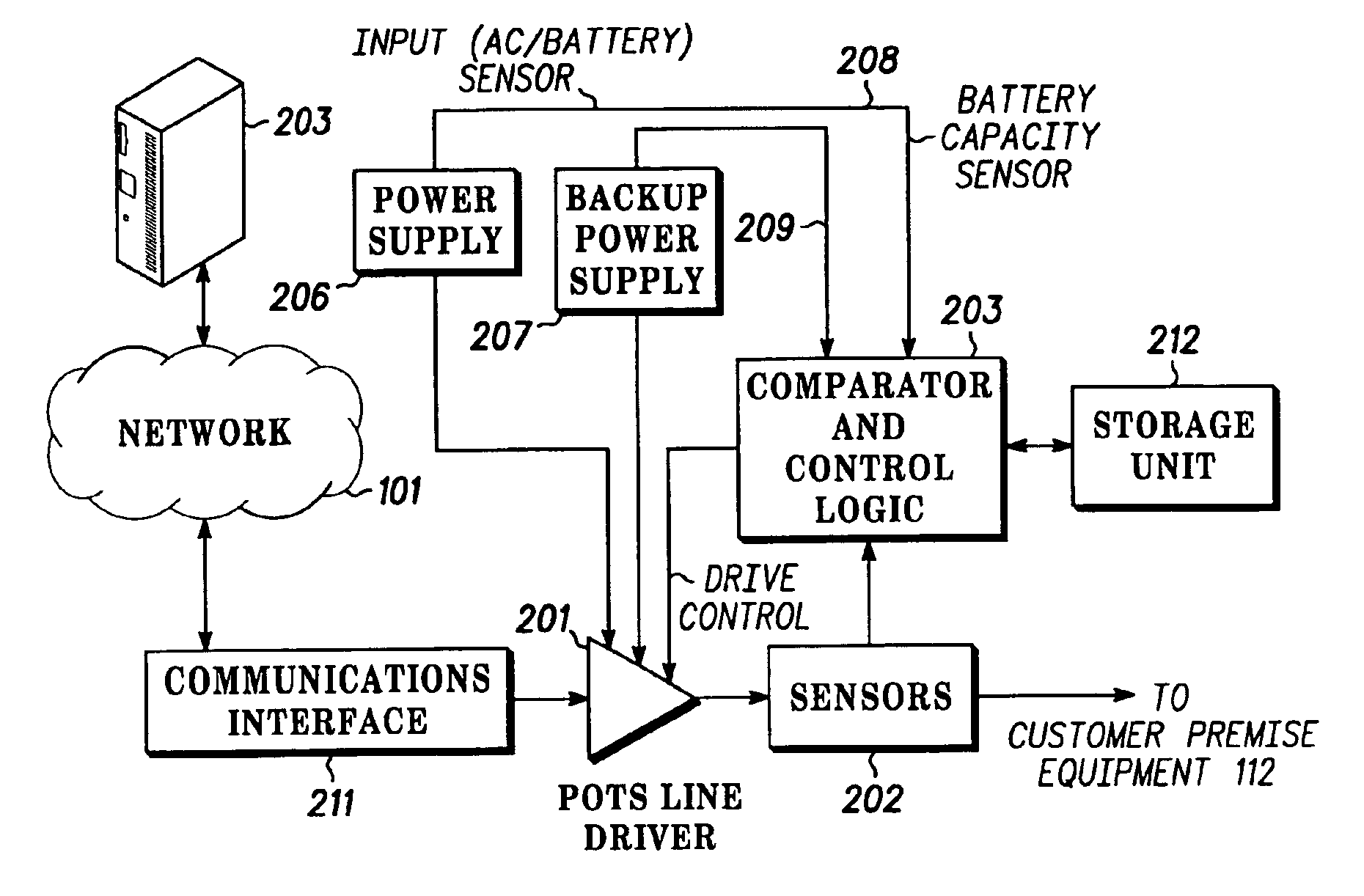
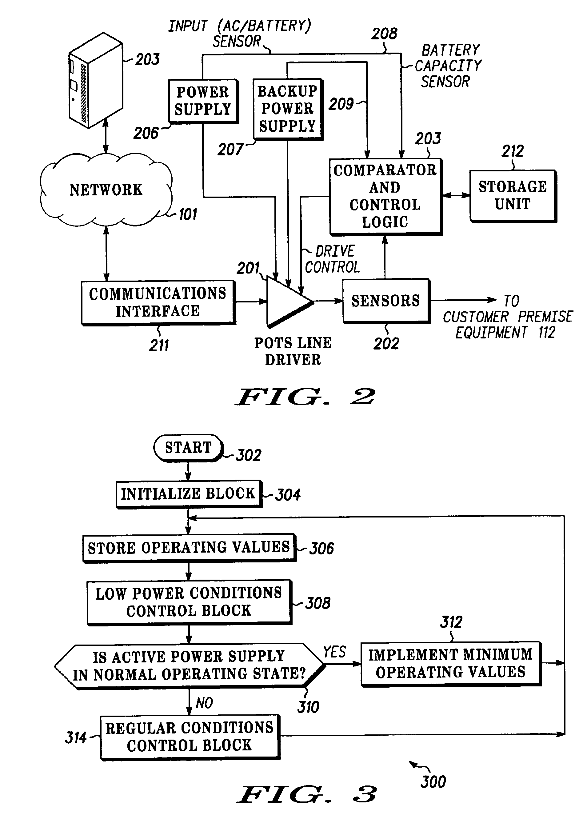
A programmable access point (110) has a line driver (201), sensors (202), comparator and control logic (203), a power supply (206), and a backup power supply (207). The line driver (201) provides power and communications signals to attached customer equipment and receives its power from either the power supply (206) or the backup power supply (207). The power supplies (206, 207) generate power supply status signals which include a signal indicating whether line driver (201) is receiving power from the power supply (206) or the backup power supply (207) and a signal indicating the reserve capacity of the backup power supply (207). The sensors (202) monitor the power output by the line driver (201). The comparator and control logic (203) receives the power supply status signals and the monitored power output values and generates a control value for line driver (201) which it provides to the line driver (201) which modifies its output responsive to the control value.

Description

BACKGROUND OF THE INVENTION[0001]1. Field of the Invention[0002]The present invention relates to telecommunication networks, and more particularly to dynamic power adjustment in telecommunications network power management.[0003]2. Background Description[0004]Generally, a telecommunications network links together distributed communications equipment such as telephones, facsimile machines, modems, and the like which all may be located on a customer's premises. In a typical telecommunications network such as a telephone network or plain old telephone service (POTS), a central network communicates with each customer's premises through an access point. The access point normally supplies power to any connected communications equipment at the particular customer's premises. The level of power supplied is typically set for the maximum rated load for the access point, i.e., the largest number of telecommunications devices, e.g., telephones, that are to be allowed to be in simultaneous use. C...

Claims


Application Information

Patent Timeline
Patent Type & Authority Patents(United States)
IPC IPC(8): H04M19/00H04M19/08H04M19/02
CPCH04M19/02H04M19/08
Inventor FREYMAN, PHILLIP KENTBACH, CHRISTOPHER R.
Owner ARRIS ENTERPRISES LLC
Learn More