
Finger operated switch for controlling a surgical handpiece

a handpiece and finger-operated technology, applied in the field of finger-operated switches for controlling the handpiece of the human operator, can solve the problem of fatigue in the finger of the human operator of the handpi

Inactive Publication Date: 2005-09-20
ETHICON ENDO SURGERY INC
View PDF23 Cites 1693 Cited by
  • Summary
  • Abstract
  • Description
  • Claims
  • Application Information

AI Technical Summary

Benefits of technology

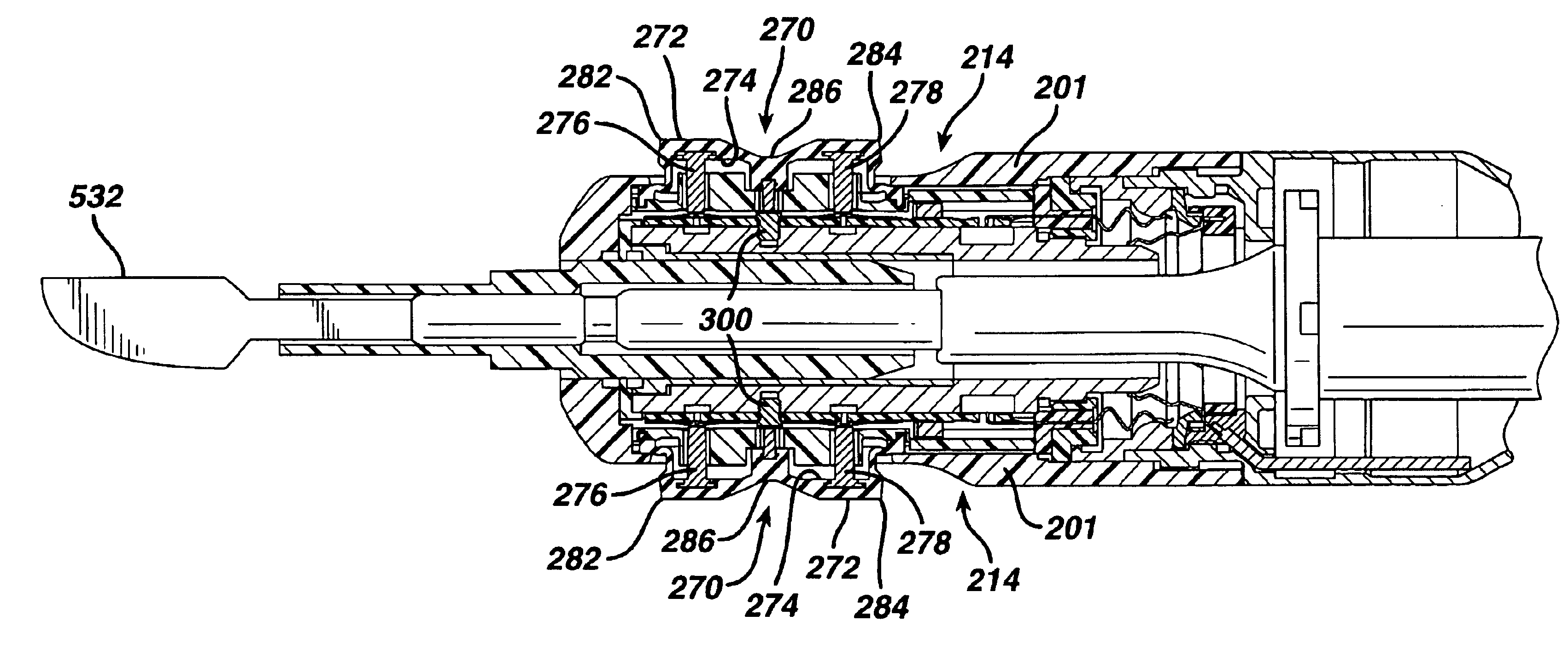
[0008]According to the invention, a finger-operated switch for activating and operating an ultrasonic surgical handpiece is provided. The power output of the surgical handpiece is responsive and proportional (linearly, nonlinearly proportional or in terms of a step function) to the pressure applied to the finger-operated switch. The finger-operated switch may include, but is not limited to: (1) electro-mechanical switches; (2) force sensitive resistors whose resistance is proportional to the force applied by the finger of the human operator of the surgical handpiece; (3) force sensitive capacitors whose capacitance is proportional to the pressure, deflection or compression of the insulation layer between two electrodes or is proportional to the spacing between the two conductive layers; (4) strain gauges mounted underneath or integral to the housing of the surgical handpiece such that the pressure applied thereto results in an output change in the strain gauges; (5) magnets or ferromagnets encased or embedded in an elastomer with a sensor inside the surgical handpiece that detects the field strength of the magnet and monitors changes relative to the force applied to the handpiece housing; and (6) piezo film or piezo ceramic material whose charge or voltage is proportional to the force applied.

Problems solved by technology

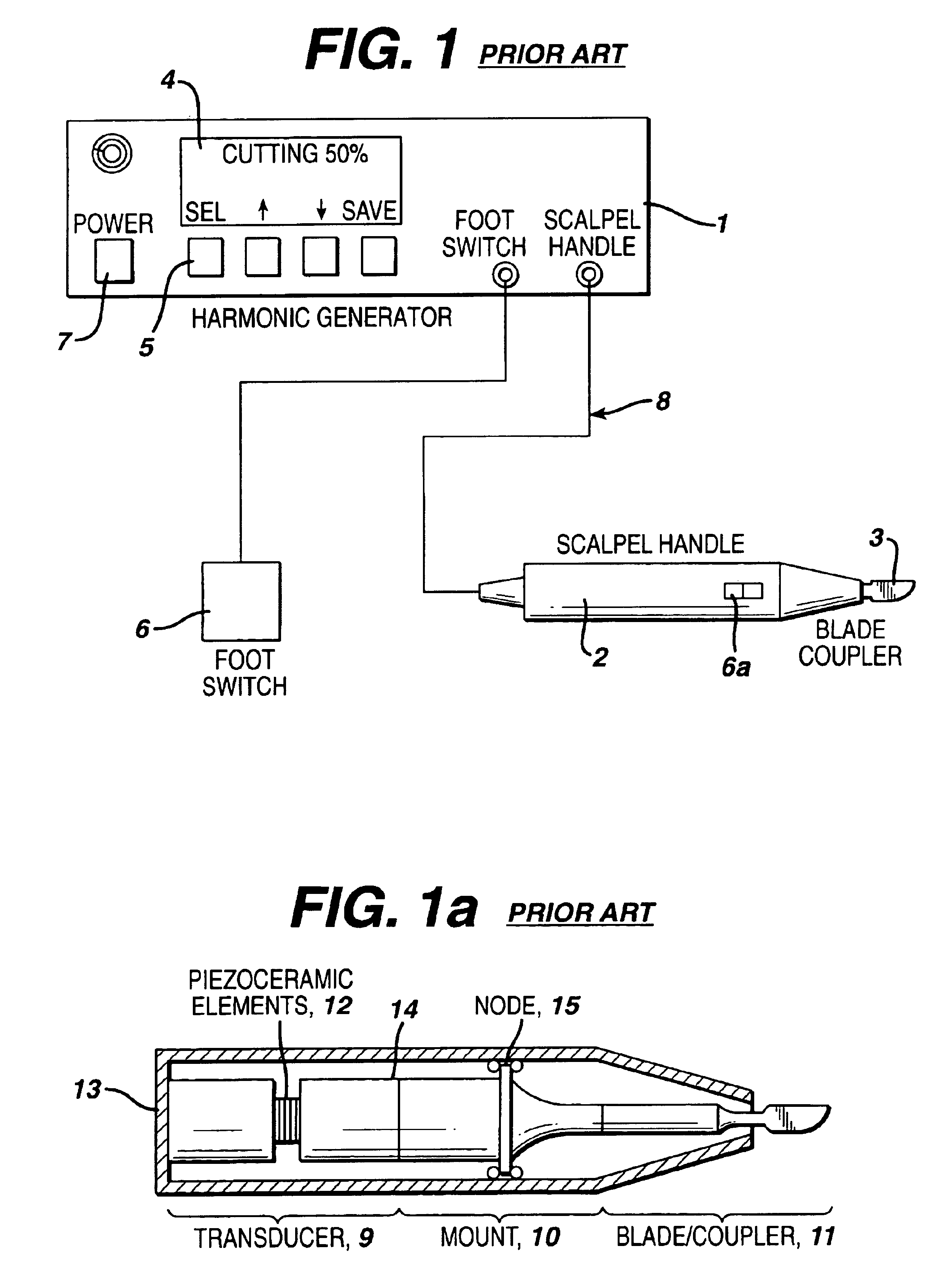
In addition, long-term operation results in fatigue in the finger of the human operator of the handpiece 2.

Method used


Image

  • Finger operated switch for controlling a surgical handpiece
  • Finger operated switch for controlling a surgical handpiece
  • Finger operated switch for controlling a surgical handpiece

Examples


Embodiment Construction

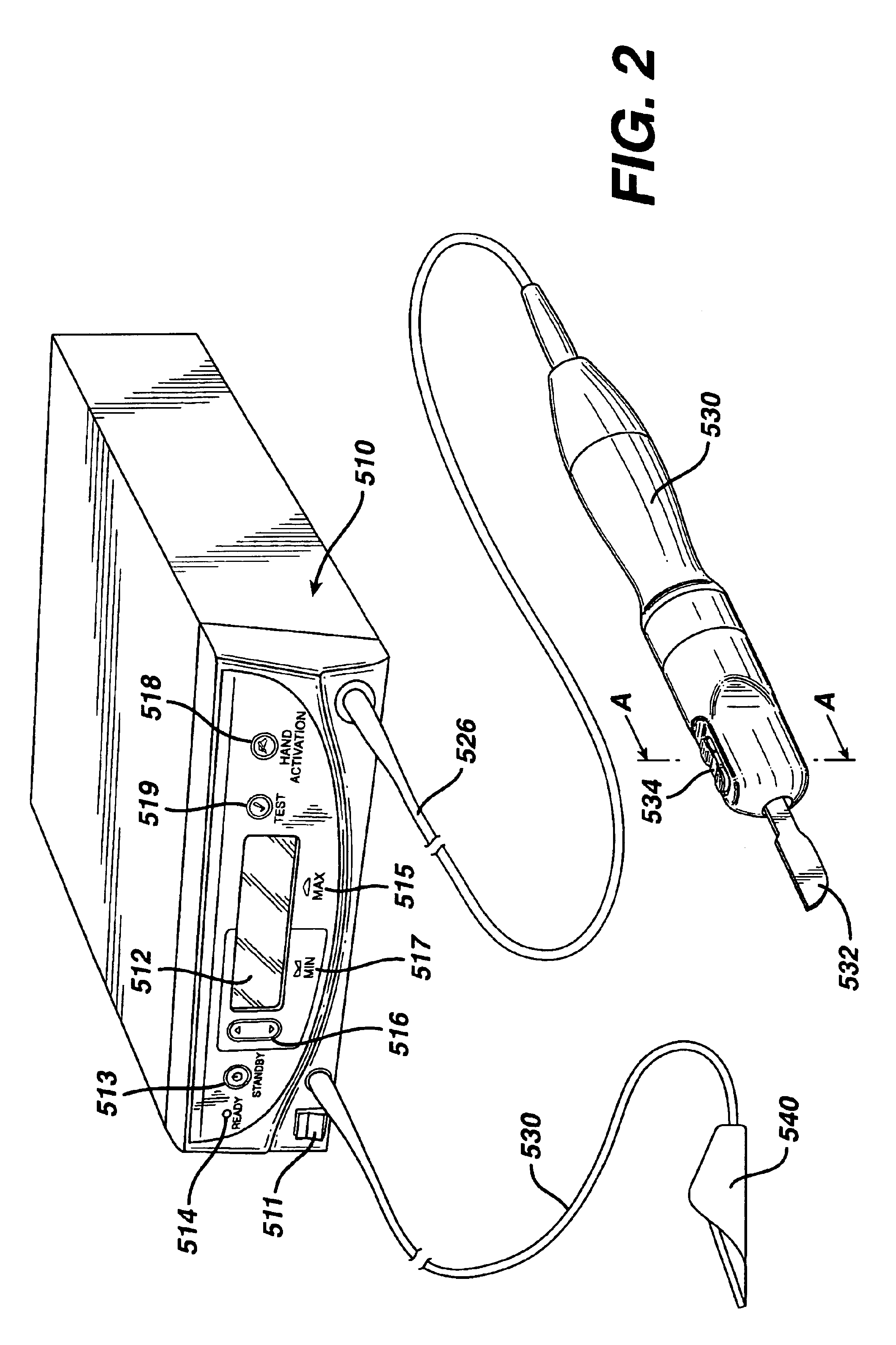
[0023]FIG. 2 is an illustration of a system for implementing surgical procedures according to the invention. By means of a first set of wires in cable 526, electrical energy, i.e., drive current, is sent from the generator console 510 to a handpiece 530 where it imparts ultrasonic longitudinal movement to a surgical device or end effect or, such as a sharp scalpel blade 532. This blade can be used for simultaneous dissection and cauterization of tissue. The supply of ultrasonic current to the handpiece 530 may be under the control of a distally located switch 534 located on the handpiece, which is connected to the generator in console 510 via wires in cable 526. The generator may also be controlled by a foot switch 540, which is connected to the console 510 by another cable 550. Thus, in use a surgeon may apply an ultrasonic electrical signal to the hand piece, causing the blade to vibrate longitudinally at an ultrasonic frequency, by operating the switch 534 on the handpiece with h...


PUM


Abstract

According to the invention, a finger-operated switch for activating and operating an ultrasonic surgical handpiece is provided. The power output of the surgical handpiece is responsive and proportional to the pressure applied to the finger-operated switch. The finger-operated switch includes, but not limited to, force sensitive resistors whose resistance is proportional to the force applied by the finger of the human operator of the surgical handpiece, force sensitive capacitors whose capacitance is proportional to the pressure, deflection or compression of the insulation layer between two electrodes or is proportional to the spacing between the two conductive layers, strain gauges mounted underneath or integral to the housing of the surgical handpiece such that the pressure applied thereto results in an output change in the strain gauges, magnets or ferromagnets encased or embedded in an elastomer with a sensor inside the surgical handpiece that detects the field strength of the magnet and monitors changes relative to the force applied to the handpiece housing, and piezo film or piezo ceramic whose charge or voltage is proportional to the force applied.

Description

RELATED APPLICATIONS[0001]The present application relates to, and claims priority of, U.S. Provisional Patent Application Ser. No. 60 / 242,159 filed on Oct. 20, 2000 and commonly assigned to the same assignee as the present application, having the title FINGER OPERATED SWITCH FOR CONTROLLING A SURGICAL HANDPIECE, which is incorporated herein by reference.FIELD OF THE INVENTION[0002]The invention generally relates to the field of medical or surgical instruments and, more particularly, to a novel finger-operated switch for controlling a medical or surgical handpiece.DESCRIPTION OF THE RELATED ART[0003]Ultrasonic medical or surgical instruments have gained widespread acceptance in the microsurgical field for use in the fragmentation and removal of body tissue. A typical ultrasonic instrument includes an ultrasonic transducer housed in a handpiece. The ultrasonic transducer is operable for converting electrical energy supplied thereto into high-velocity vibrational movements. The transdu...

Claims


Application Information

Patent Timeline
Patent Type & Authority Patents(United States)
IPC IPC(8): A61B17/32A61B17/00A61B18/00H01H13/00
CPCA61B17/320068A61B2017/00367H01H2300/014H01H2300/022A61B2017/320069A61B2017/320071A61B2017/320089
Inventor DONOFRIO, WILLIAM T.HARPER, RICHARD M.BORN, JASON A.SCHWEMBERGER, RICHARD F.GILL, ROBERT P.SCHRAMM, MARY E.
Owner ETHICON ENDO SURGERY INC
Learn More