Force-based power steering system

Inactive Publication Date: 2005-09-20
TECHCO
View PDF9 Cites 25 Cited by
  • Summary
  • Abstract
  • Description
  • Claims
  • Application Information

AI Technical Summary

Benefits of technology

[0011]It is desirable for working pressures in the power cylinder to always be kept at the lowest pressure values possible. Thus pressure values applied to various power cylinder seals are kept to a minimum thereby reducing leakage problems and minimizing Coulomb friction. Thus preferably, the present invention also comprises a two-position three-way valve for fluidly coupling the cylinder port having the lowest pressure value to the reservoir. The two-position three-way valve is configured and functions in exactly the same manner as three-way valve (39) of the incorporated '254 patent. However, as a consequence of fluidly coupling the cylinder port having the lowest pressure value to the reservoir it is then necessary for the electronically controlled closed-center control valve assembly to separately supply fluid to the first and second cylinder ports in order to preclude the possibility of accumulator-sourced fluid directly flowing to the reservoir via the two-position three-way valve.
[0013]In addition, it is also desirable to fluidly couple both of the left and right cylinder ports to the reservoir during “on-center” steering conditions whereat nominal zero valued desired power cylinder differential pressure values are required anyway. This improves overall system efficiency by allowing small on-center steering motions to be effected without using any accumulator-sourced fluid. An electronically controlled, spring-loaded, compound two-way valve is provided for this purpose. The spring-loaded feature serves along with the biasing feedback spring feature described above (e.g., with respect to the electronically controlled three-way control valves) as a fail-safe mechanism whereby the left and right cylinder ports are fluidly connected to the reservoir in the event of any system failure. The compound two-way valve is of course progressively closed as steering wheel torque is increased (e.g., in either direction) in order to permit differential pressure to be applied to the power cylinder.
[0021]In a fifth aspect, the present invention is directed to a method for enabling a power steering system utilizing an accumulator, a reservoir, a two-position three-way valve for fluidly coupling the cylinder port having the lowest pressure value to the reservoir, and first and second electronically controlled three-way closed-center control valves, to function in the manner of a force-based power steering system, wherein the method comprises the steps of: measuring values of torque applied to the steering wheel of a host vehicle; determining polarity of and measuring instant differential pressure values actually present between the first and second ports of the power cylinder; determining desired polarity and instant differential pressure values to be applied between first and second ports of the power cylinder in response to a selected function of the instant applied torque value, vehicle speed and any other desired system input factors; subtracting instant differential pressure values from the desired instant differential pressure values to form an error signal; amplifying the error signal to form a control signal; selecting an appropriate one of the first and second electronically controlled three-way closed-center control valves in accordance with the polarity of the actual instant differential pressure value between the first and second ports of the power cylinder; and operating the selected electronically controlled three-way closed-center control valve in response to the control signal so as to continually reduce the error signal and thus provide the desired instant differential pressure values between the first and second ports of the power cylinder.
[0022]Because of its improved steering feel and ability to service known future power steering systems whose net hydraulic power requirements range as high as 3,500 Watts, a power steering system configured according to the present invention possesses distinct advantages over known prior art power steering systems able to handle such large steering loads. For example, the power steering system of the present invention provides dramatically improved system efficiency when compared to standard hydraulic power steering systems utilizing engine driven pumps. Further, the power steering system of the present invention provides dramatically improved tactile feel when compared to known prior art accumulator and closed-center valve enabled power steering systems. Thus, the power steering systems of the present invention enable both efficient and tactilely acceptable power steering for large vehicles.

Problems solved by technology

While the EPS system described in the incorporated '254 patent has optimum performance characteristics, it like all EPS systems is limited in utilization to relatively small vehicles because of limited available electrical power.
All vehicle manufacturers limit electrical current availability for EPS systems to a value that can be supplied directly from an alternator.
To date however, none of the proposed closed-center power steering systems has provided acceptable on-center steering “feel” and they have not gained acceptance in the industry.
It is believed herein that the primary problem with the closed-center power steering systems proposed to date is that their fundamental output is fluid flow or rate-based rather than force-based as is described above with reference to currently accepted power steering systems.
It is believed herein that these discontinuities in system acceleration are the root cause of the unacceptable on-center steering feel in the closed-center power steering systems.

Method used


Image

  • Force-based power steering system
  • Force-based power steering system
  • Force-based power steering system

Examples


Embodiment Construction

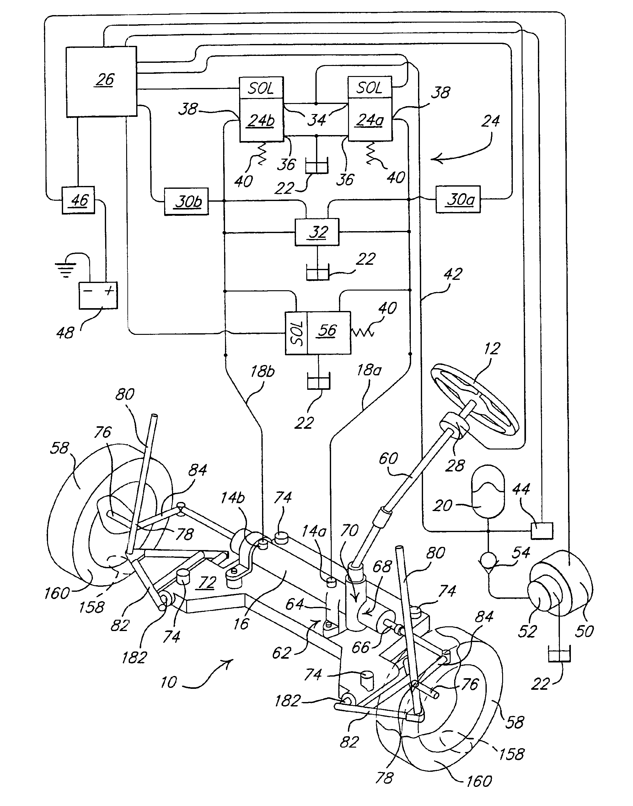
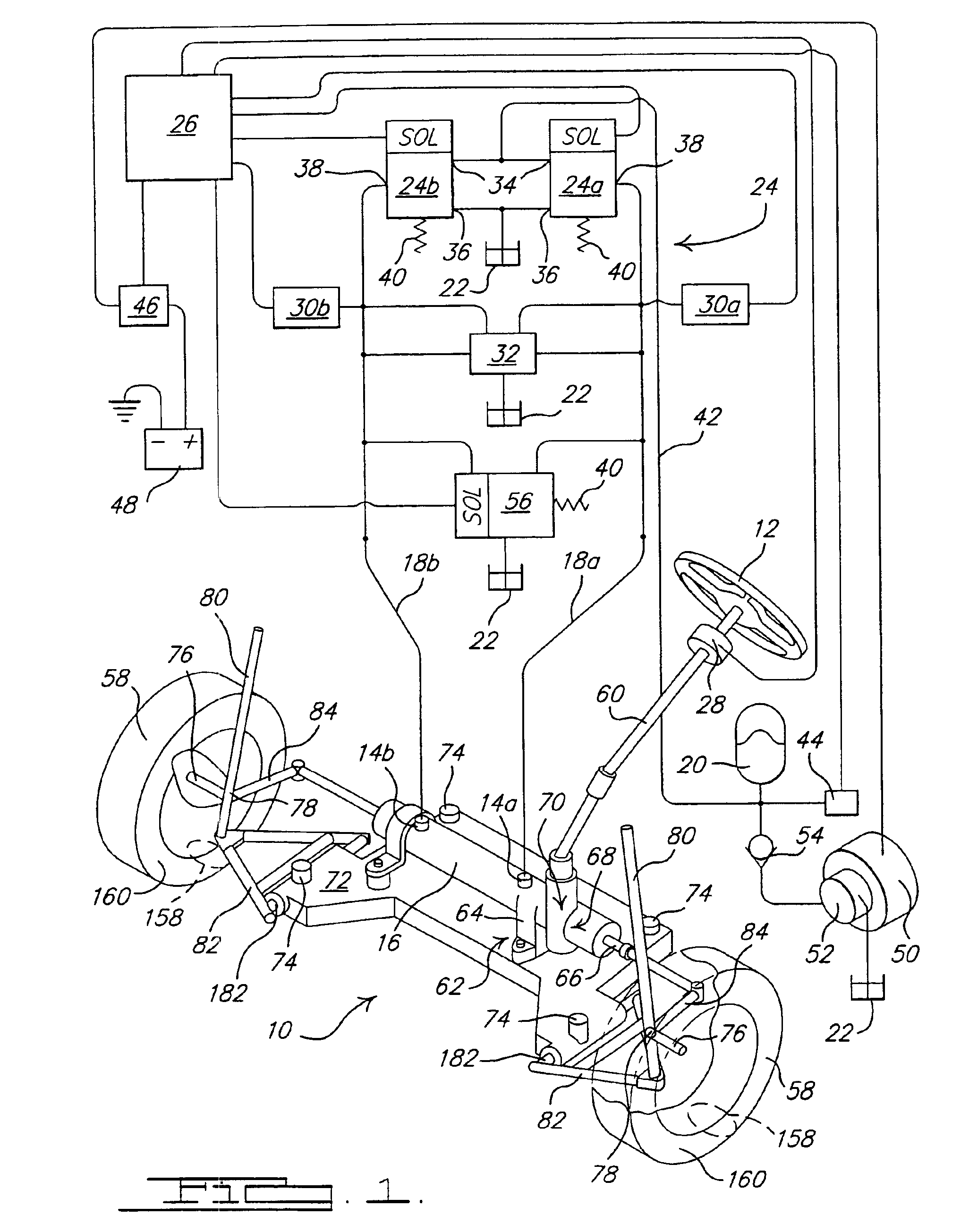
[0028]The present invention is directed to method and apparatus for enabling an accumulator and closed-center valve enabled power steering system to function in the manner of a force-based power steering system. With reference first to FIG. 1, there shown is a schematic view depicting operative elements of a power steering system 10 wherein torque applied by a driver to a steering wheel 12 results in differential pressure being applied to first and second ports 14a and 14b of a double-acting power cylinder 16 via first and second fluid lines 18a and 18b, respectively. Controlled amounts of pressurized fluid issuing from an accumulator 20 or returning to a reservoir 22 are metered to or from first and second fluid lines 18a and 18b via an electronically controlled closed-center control valve assembly 24 in response to control signals issuing from a controller 26.

[0029]The accumulator 20 is initially and then intermittently charged with fluid such that the accumulator fluid pressure i...


PUM


Abstract

Apparatus and method is presented for enabling a power steering system comprising an accumulator, a reservoir, and an electronically controlled closed-center control valve assembly for selectively fluidly coupling the accumulator and reservoir to a double-acting power cylinder of a power steering system to function in the manner of a force-based power steering system.

Description

RELATED APPLICATION[0001]This application claims priority of U.S. Provisional Patent Application Ser. No. 60 / 474,093 filed May 29, 2003.BACKGROUND OF THE INVENTION[0002]The present invention relates generally to power steering systems for vehicles, and more particularly to an electrically powered steering system intended for large vehicles.[0003]Virtually all present power steering systems comprise implementation means whose fundamental output is force based. By way of example, present art power steering systems generally comprise a common open-center valve that delivers differential pressure to a double-acting power cylinder as a function of torque applied to a steering wheel. This is accomplished via the steering wheel progressively closing off return orifices comprised within the open-center valve. Another example is an electric power steering system (hereinafter “EPS system”) wherein a servo-motor delivers torque as a function of current applied to it by a controller. An EPS sys...

Claims


Application Information

Patent Timeline
IPC IPC(8): B62D5/06B62D5/09B62D6/00B62D5/065
CPCB62D5/065B62D5/09B62D6/00
Inventor PHILLIPS, EDWARD H.
Owner TECHCO
Why Eureka
Try Eureka