Method for operating an internal combustion engine having a compressor

Inactive Publication Date: 2005-09-20
ROBERT BOSCH GMBH
View PDF5 Cites 5 Cited by
  • Summary
  • Abstract
  • Description
  • Claims
  • Application Information

AI Technical Summary

Benefits of technology

[0004]The method of the invention is for operating an internal combustion engine and affords the advantage compared to the foregoing that a check is made in at least one operating state of the engine as to whether a pumping of the compressor occurs and that the pump limit is corrected in dependence upon the check result. In this way, the pump limit can be made current during the operation of the engine. A safety spacing for limiting the desired value for the charge-air pressure, which considers the unit scattering and deterioration effects of the compressor, is then no longer necessary. With the continuous actualization or learning of the pump limit during the operation of the engine, the compressor can be utilized in the entire permissible range of the compressor characteristic field. The desired value for the charge-air pressure can be so selected that pressure ratios across the compressor are possible which come very close to the pump limit without the safety spacing because the unit scattering and the deterioration effects of the compressor are considered by the actualization of the pump limit. In this way, the compressor can be used in a greater range of the compressor characteristic field without the pump limit being exceeded and without disturbing noises occurring or increased material load because of the compressor pumping.
[0005]It is especially advantageous when the occurrence of the pumping is detected in dependence upon the amplitude of a fresh air mass, which is supplied to the engine and oscillates at a pregiven frequency. In this way, an especially reliable possibility is provided to detect an occurrence of the compressor pumping.
[0006]A further advantage is that the amplitude of the oscillating fresh air mass is determined by means of a discrete Fourier transformation of a scanned signal sequence of a detected fresh air mass. This defines a simple and rapid possibility for determining the amplitude.

Problems solved by technology

If the pressure ratio exceeds the pump limit, then this leads to an intense oscillation of the fresh air mass supplied to the engine.
In this way, the operating range of the compressor in the compressor characteristic field is limited.

Method used


Image

  • Method for operating an internal combustion engine having a compressor
  • Method for operating an internal combustion engine having a compressor
  • Method for operating an internal combustion engine having a compressor

Examples


Embodiment Construction

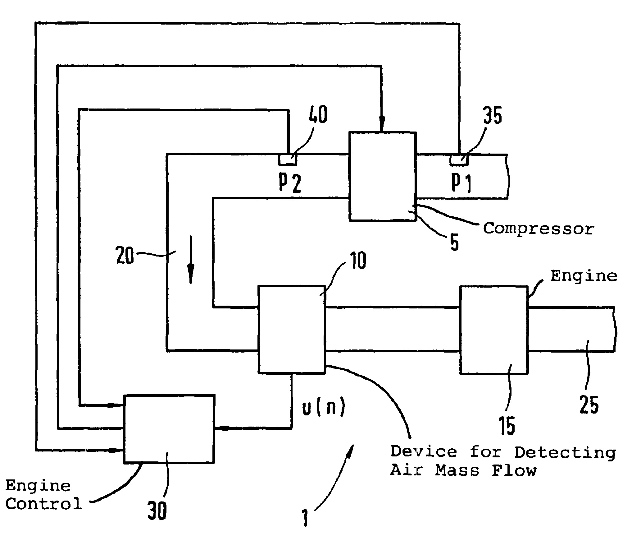
[0018]In FIG. 1, reference numeral 1 identifies an internal combustion engine, for example, of a motor vehicle. Fresh air is inducted via an air system 20 and supplied to an engine 15 including at least one cylinder. The flow direction of the fresh air is indicated by an arrow. The exhaust gas, which results from the combustion in the engine 15, is supplied to an exhaust-gas system 25. In the air system 20, a compressor 5 is mounted which, for example, can be a compressor of an exhaust-gas turbocharger or an electrically driven compressor or a compressor driven by a crankshaft of the engine 15. The pressure in the air system 20 in flow direction ahead of the compressor 5 is identified in FIG. 1 by p1. The pressure in the air system 20 in flow direction downstream of the compressor 5 is identified in FIG. 1 by p2. The pressure ratio across the compressor 5 is therefore p2 / p1. The pressure p2 is therefore the charge-air pressure and p1 is the intake pressure. A device 10 for detecting...


PUM


Abstract

The invention is directed to a method for operating an internal combustion engine (1) having a compressor (5) which method makes possible an actualization of a pump limit of the compressor (5). A pressure ratio across the compressor (5) is limited in dependence upon a mass flow through the compressor (5) by means of the pump limit in order to prevent a pumping of the compressor (5). In at least one operating state of the engine (1), a check is made as to whether a pumping of the compressor (5) occurs. The pump limit is corrected in dependence upon the test results.

Description

BACKGROUND OF THE INVENTION[0001]Methods are known for operating an internal combustion engine having a compressor, especially a turbocharger. A pressure ratio across the compressor is limited by means of a pump limit in dependence upon a mass flow through the compressor in order to prevent a pumping of the compressor. If the pressure ratio exceeds the pump limit, then this leads to an intense oscillation of the fresh air mass supplied to the engine. This becomes noticeable from a pulsating noise which is based on the so-called charger pumping or compressor pumping. The pump limit defines the limit of a compressor characteristic field starting from which the compressor characteristic field is no longer defined. The compressor characteristic field determines the permissible pressure ratio across the compressor in dependence upon the mass flow through the compressor. In FIG. 3, a compressor characteristic field is shown by way of example wherein the pressure ratio is plotted against a...

Claims


Application Information

Patent Timeline
IPC IPC(8): F02D23/00F02B37/12F02D41/18F02D41/00F02B33/32F02B33/00F02B39/16F02D45/00
CPCF02B37/12F02D23/00F02B33/32F02D41/0007F02D41/18Y02T10/144Y02T10/12
Inventor BLEILE, THOMASSCHEIDT, MICHAEL
Owner ROBERT BOSCH GMBH
Why Eureka
Try Eureka