Eureka AIR delivers breakthrough ideas for toughest innovation challenges, trusted by R&D personnel around the world.

Automated rig control management system

a management system and rig technology, applied in the direction of seismology for waterlogging, using reradiation, instruments, etc., can solve the problems of prone to errors, affecting the production capacity of boreholes, and affecting the drilling service provided by contractors

Active Publication Date: 2005-09-13
VARCO I P INC
View PDF8 Cites 127 Cited by
  • Summary
  • Abstract
  • Description
  • Claims
  • Application Information

AI Technical Summary

Benefits of technology

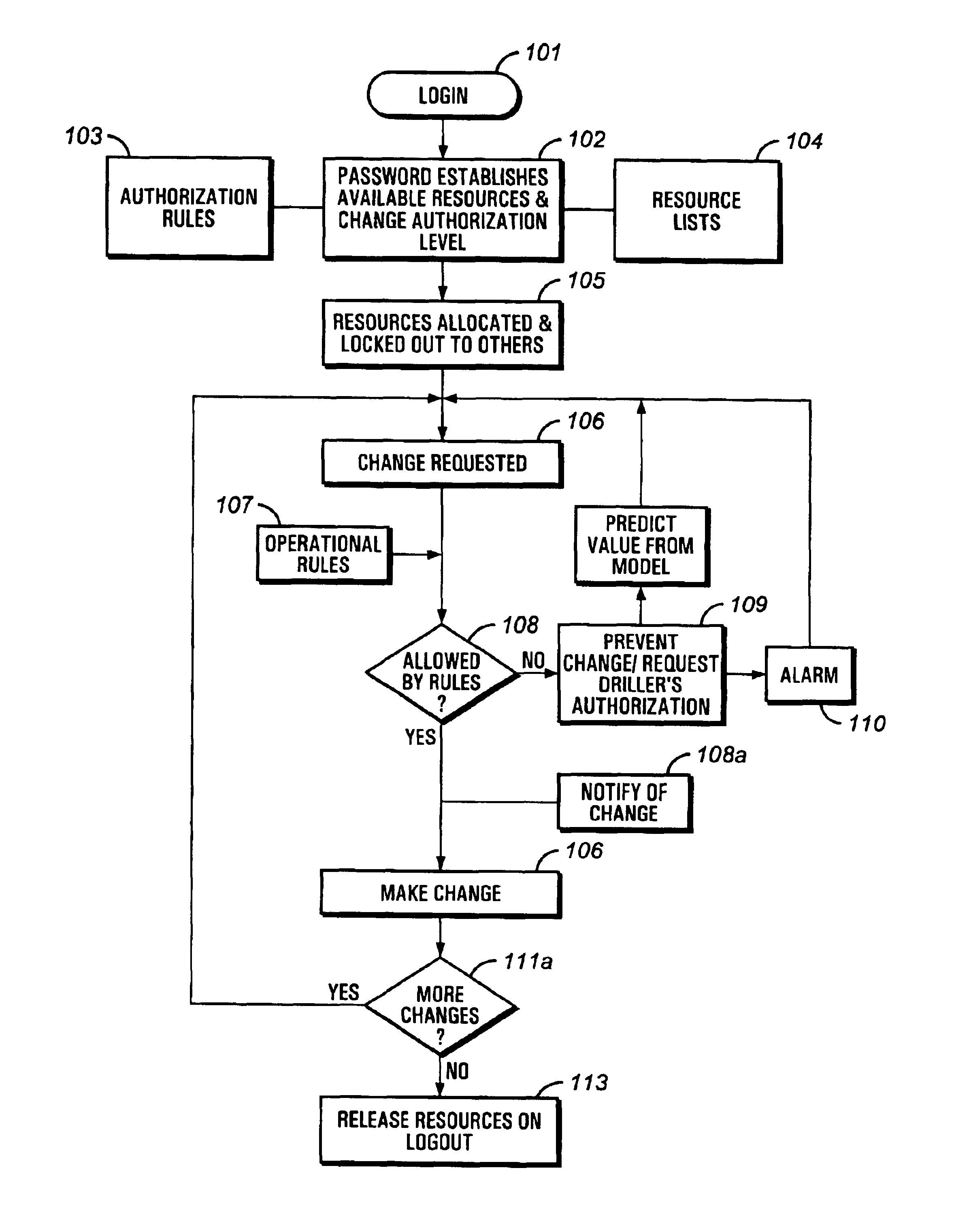
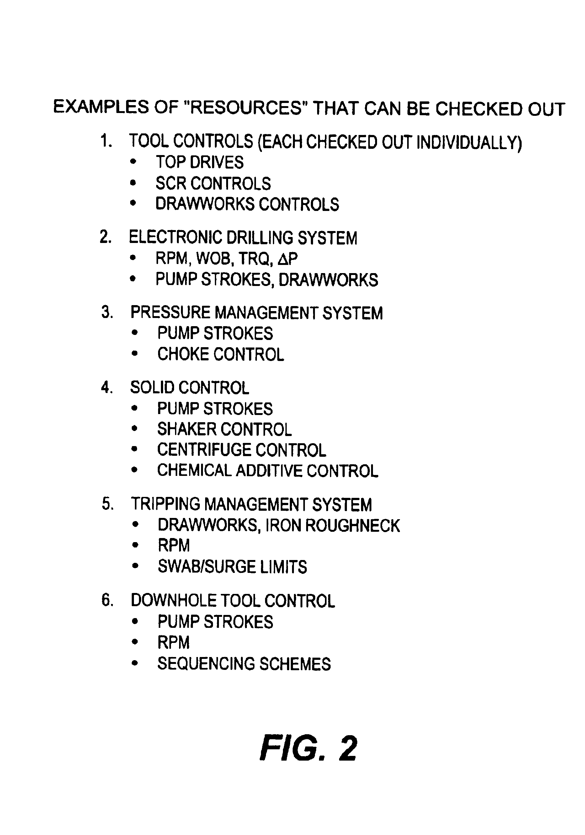
[0015]The methods of the present invention overcome the foregoing disadvantages of the prior art by providing an automated rig control management system having a hierarchical and authenticated communication interface to the various service contractor and rig operation inputs and using a control model for allocating and regulating rig resources according to operating rules programmed into the control management system to achieve the desired well plan within the operational constraints of the drilling rig equipment and borehole.
[0016]In one aspect of the present invention, a method for controlling operation of a drilling rig having a control management system, comprises programming the control system with at least one resource module, the at least one resource module having at least one operating model having at least one set of programmed operating rules related to at least one set of operating parameters. In addit...

Problems solved by technology

Yet another service contractor may be providing underbalanced drilling services.
However, this action may cause internal pressures of the borehole to rise above desirable limits resulting in a degradation of the producing capability of the borehole once drilling is completed.
This process is prone to error.
For example, instructions may be misinterpreted by the rig operator, or misinterpreted by the drilling crew to which they are communicated, and executed improperly.
Or, the instructions may not be passed on correctly to subsequent drilling crews on subsequent work shifts.
Even when such recommendations are successfully resolved and communicated properly to the rig operator, it is still an inefficient process, which wastes potentially productive time in meetings and getting necessary authorizations.
However, these systems do not provide any mechanism for accommodating more than one person to control various aspects of the drilling operation.
As noted above, this arrangement becomes problematic as drilling processes advance in complexity.
As noted above, decisions regarding the ideal settings for control parameters are increasingly not made by the driller, and current methods for funneling the needed information to the driller are fraught with difficulties.

Method used


Image

  • Automated rig control management system
  • Automated rig control management system
  • Automated rig control management system

Examples


Embodiment Construction

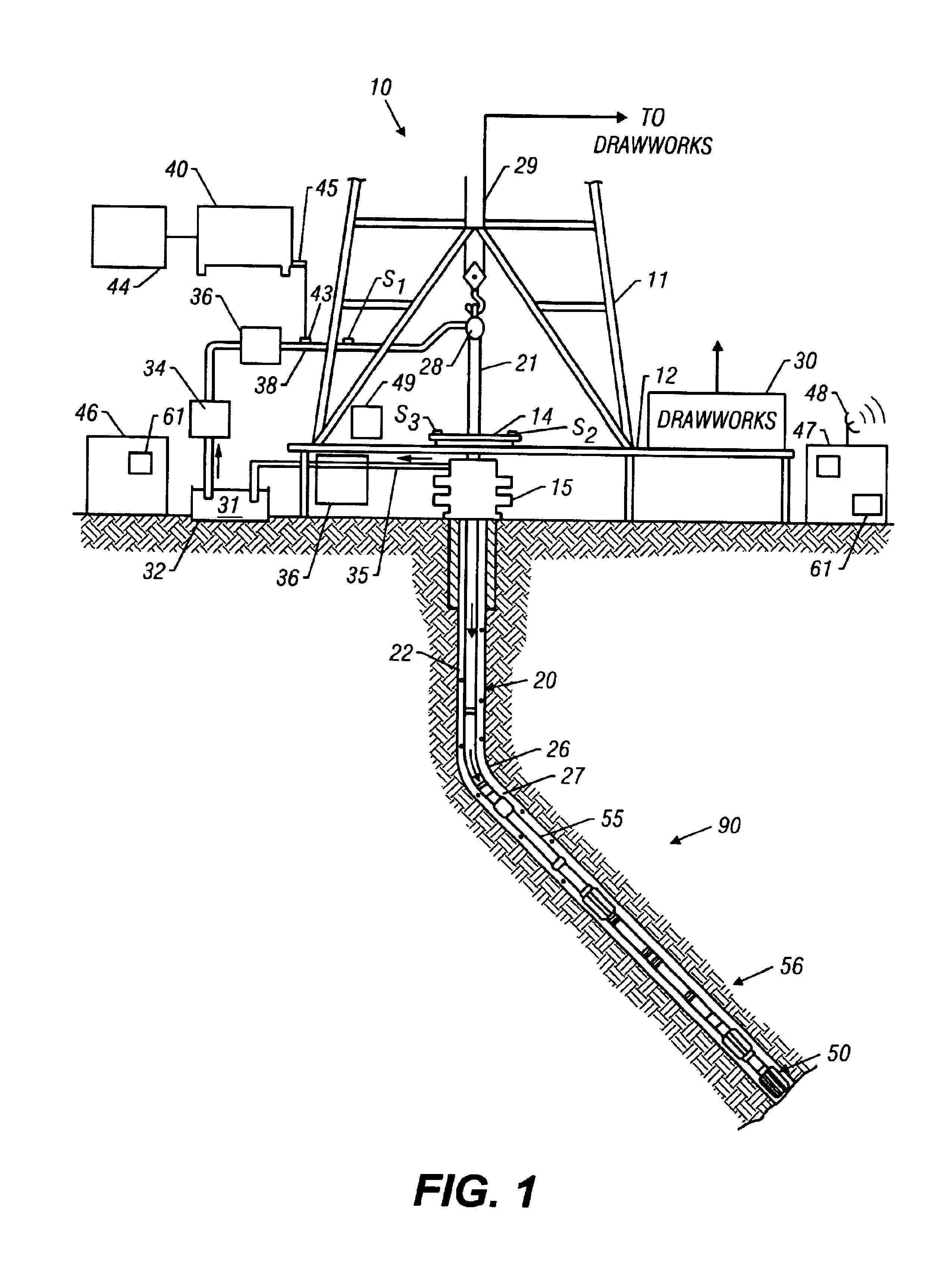
[0027]FIG. 1 shows a schematic diagram of an exemplary drilling system 10 having a drilling assembly 90 shown conveyed in a borehole 26 for drilling the wellbore. The drilling system 10 includes a conventional derrick 11 having a floor 12 which supports a rotary table 14 that is rotated by a prime mover such as an electric motor (not shown), controlled by a motor controller (not shown) at a desired rotational speed. The motor controller may be a silicon controlled rectifier (SCR) system known in the art. The drill string 20 includes a drill pipe 22 extending downward from the rotary table 14 through a pressure control device 15 into the borehole 26. The pressure control device 15 is commonly hydraulically powered and may contain sensors (not shown) for detecting operating parameters and controlling the actuation of the pressure control device 15. A drill bit 50, attached to the drill string end, disintegrates the geological formations when it is rotated to drill the borehole 26. The...


PUM


Abstract

A system and method for controlling operation of a drilling rig having a control management system, comprises programming the control system with at least one resource module, the at least one resource module having at least one operating model having at least one set of programmed operating rules related to at least one set of operating parameters. In addition, the system and method provide an authenticating hierarchical access to at least one user to the at least one resource module.

Description

CROSS-REFERENCE TO RELATED APPLICATIONS[0001]This application claims the priority of U.S. Provisional Patent application Ser. No. 60 / 398,670 filed Jul. 26, 2002.BACKGROUND OF THE INVENTION[0002]1. Field of the Invention[0003]This invention relates generally to systems for drilling boreholes for the production of hydrocarbons and more particularly to an automated rig control management system having a hiearchical and authenticating communication interface to the various service contractor and rig operation inputs and using a control model for allocating and regulating rig resources according to operating rules programmed into the control management system to achieve the desired well plan within the operational constraints of the drilling rig equipment and borehole.[0004]2. Description of the Related Art[0005]To obtain hydrocarbons such as oil and gas, boreholes are drilled by rotating a drill bit attached at a drill string end. A large proportion of the current drilling activity invo...

Claims


Application Information

Patent Timeline
IPC IPC(8): E21B44/00
CPCE21B44/00
Inventor WOMER, KEITHKOEDERITZ, WILLIAM I.GUGGARI, MALLAPPA I.
Owner VARCO I P INC
Why Eureka
Eureka Blog
Learn More