
Method and apparatus for determining a layer 2 path in a switched network

a switched network and path technology, applied in the field of computer network management, can solve problems such as insufficient knowledge of the physical topology of the network to diagnose an error in the network, insufficient information obtained from ip path tracing performed at layer b>3/b>, and change in characteristics of many network devices

Inactive Publication Date: 2005-09-13
CISCO TECH INC
View PDF15 Cites 56 Cited by
  • Summary
  • Abstract
  • Description
  • Claims
  • Application Information

AI Technical Summary

Benefits of technology

[0022]In another feature, concatenating the first path segment and the second path segment to result in creating and storing the subpath for the contiguous pair includes the step of eliminating extraneous devices from the first and second path segments.
[0023]In another feature, concatenating the subpaths to result in creating and storing information representing the Layer 2 path includes the step of eliminating extraneous devices from the subpaths.
[0024]According to another aspect of determining a Layer 2 path between a source device and a destination device in a switched network, the method comprises the computer-implemented steps of: determining a Layer 3 path between the source device and the destination device, wherein the Layer 3 path comprises information identifying two or more Layer 3 devices; identifying contiguous pairs of Layer 3 devices in the Layer 3 path; determining a subpath for each contiguous pair of Layer 3 devices in the Layer 3 path; determining whether any contiguous pair of Layer 3 devices has no subpath; concluding that there is no Layer 2 path when any contiguous pair of Layer 3 devices has no subpath; eliminating extraneous devices in the subpaths; and concatenating the subpaths to result in creating and storing information representing the Layer 2 path when each of the contiguous pairs of Layer 3 devices has a subpath.
[0025]According to one feature of this aspect is that determining a subpath for each contiguous pair of Layer 3 devices comprises the steps of: determining a first interface on a first node of the contiguous pair that is connected to a second interface on a second node of the contiguous pair for a given subnet when both the first node of the contiguous pair and the second node of the contiguous pair have non-trunking interfaces; determining a first native VLAN of the first interface and a second native VLAN the second interface; determining whether the first native VLAN matches the second native VLAN; selecting the matching VLAN as a relevant VLAN between the first and second nodes of the contiguous pair when the first native VLAN matches the second native VLAN; gathering a current spanning tree information for the relevant VLAN; tracing a first path segment from the first node of the contiguous pair to a root of the spanning tree by following the current spanning tree information associated with the relevant VLAN to a root of the spanning tree; tracing a second path segment from the second node of the contiguous pair to the root of the spanning tree by following the current spanning tree information associated with the relevant VLAN; eliminating extraneous devices in the first and second path segments; and concatenating the first path segment and the second path segment to result in creating and storing the subpath for the contiguous pair.
[0026]In another feature, determining a subpath for each contiguous pair of Layer 3 devices comprises the steps of: determining a non-trunking node of the contiguous pair when one of the nodes of the contiguous pair for a given subnet has a non-trunking interface and the other node of the contiguous pair has a trunking interface; determining the non-trunking interface on the non-trunking node of the contiguous pair as a first interface that is connected to a second interface on the other node of the contiguous pair; determining a native VLAN on the first interface; determining whether there is an active VLAN on the second interface that matches the native VLAN on the first interface; selecting the matching VLAN as a relevant VLAN between the non-trunking node and the other node of the contiguous pair when there is an active VLAN on the second interface that matches the native VLAN on the first interface; gathering a current spanning tree information for the relevant VLAN; tracing a first path segment from the non-trunking node of the contiguous pair to a root of the spanning tree by following the current spanning tree information associated with the relevant VLAN to a root of the spanning tree; tracing a second path segment from the other node of the contiguous pair to the root of the spanning tree by following the current spanning tree information associated with the relevant VLAN; eliminating extraneous devices in the first and second path segments; and concatenating the first path segment and the second path segment to result in creating and storing the subpath for the contiguous pair.
[0027]In another feature, determining a subpath for each contiguous pair of Layer 3 devices comprises the steps of: determining a first interface on a first node of the contiguous pair that is connected to a second interface on a second node of the contiguous pair for a given subnet when both the first node of the contiguous pair and the second node of the contiguous pair have non-trunking interfaces; and determining a first active VLAN of the first interface associated with the given subnet and a second active VLAN the second interface associated with the given subnet; determining whether the first active VLAN matches the second active VLAN; selecting the matching VLAN as a relevant VLAN between the first and second nodes of the contiguous pair when the first active VLAN matches the second active VLAN; gathering a current spanning tree information for the relevant VLAN; tracing a first path segment from the first node of the contiguous pair to a root of the spanning tree by following the current spanning tree information associated with the relevant VLAN to a root of the spanning tree; tracing a second path segment from the second node of the contiguous pair to the root of the spanning tree by following the current spanning tree information associated with the relevant VLAN; eliminating extraneous devices in the first and second path segments; and concatenating the first path segment and the second path segment to result in creating and storing the subpath for the contiguous pair.

Problems solved by technology

In addition, the characteristics of many network devices may change over time.
However, knowledge of the physical topology of the network may not be sufficient for diagnosing an error in the network.
A data link path is important for network monitoring and diagnostics because the information obtained from IP path tracing performed at Layer 3 may be insufficient.
However, techniques for direct IP tracing at Layer 2 that are suitable for a wide range of technologies including Ethernet, Local Area Network Emulation, Token Ring, and EtherChannel are not available.

Method used


Image

  • Method and apparatus for determining a layer 2 path in a switched network
  • Method and apparatus for determining a layer 2 path in a switched network
  • Method and apparatus for determining a layer 2 path in a switched network

Examples


Embodiment Construction

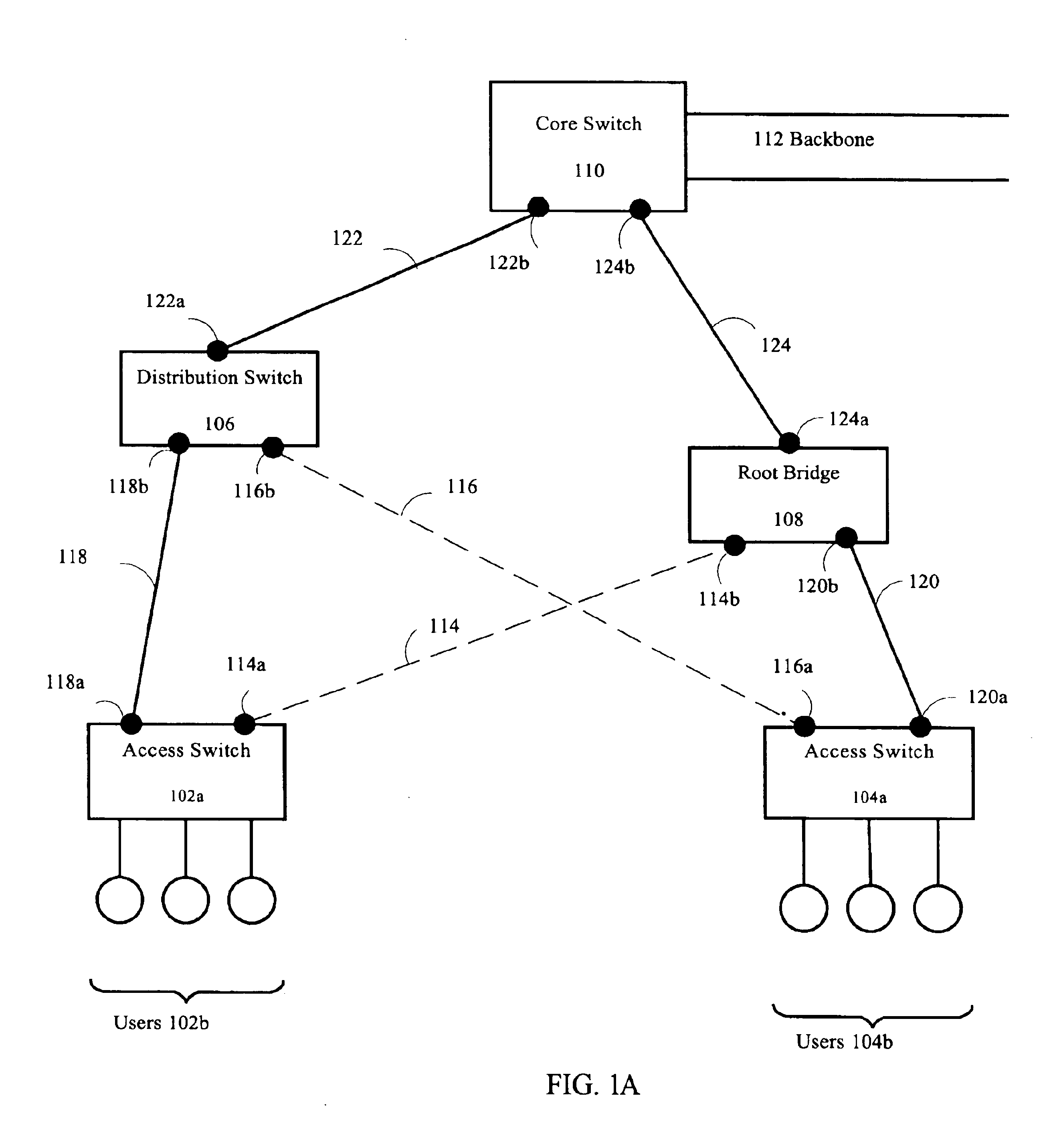
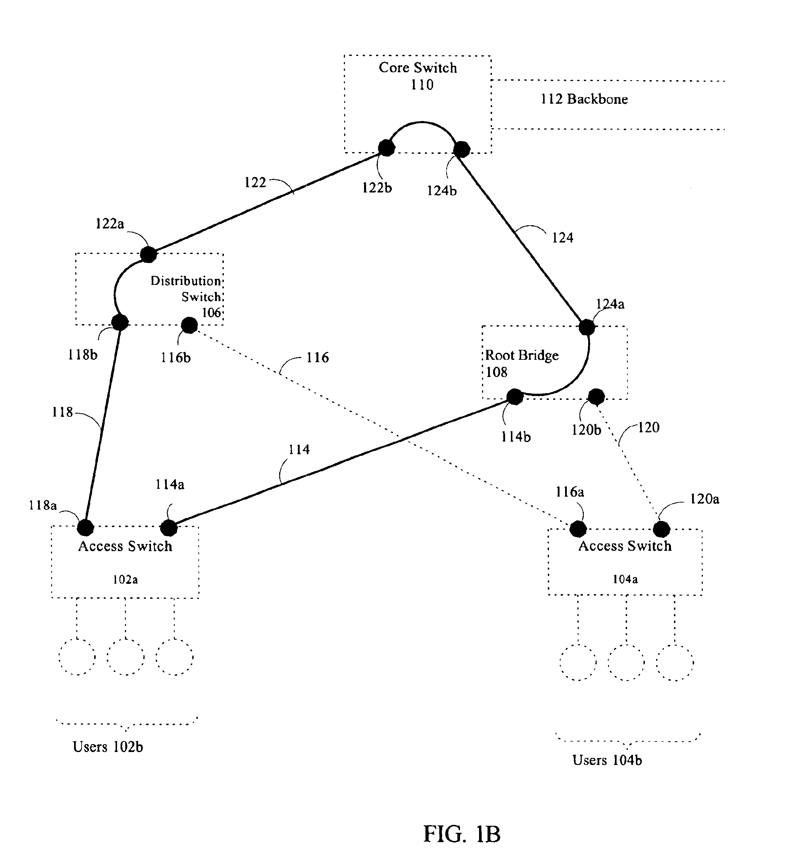
[0043]A method and apparatus for determining a Layer 2 path between two or more nodes in a switched network is disclosed herein. In the following description, for the purposes of explanation, numerous specific details are set forth in order to provide a thorough understanding of the present invention. It will be apparent, however, to one skilled in the art that the present invention may be practiced without these specific details. In other instances, well-known structures and devices are shown in block diagram form in order to avoid unnecessarily obscuring the present invention.

Overview

[0044]For purposes of illustration, the invention is described in the context of Internet Protocol (“IP”) network addressing. The IP standard specifies that each host is assigned a unique 32-bit number known as the host's IP address, which is used for all communication with the host. Each packet sent across an IP network contains the 32-bit IP addresses of the sender (source) as well as the intended r...


PUM


Abstract

A method and apparatus that provide for a Layer 2 path determination are disclosed. In one embodiment of the invention, a Layer 3 path between a source device and destination device is first determined in order to identify contiguous pairs of Layer 3 devices. A subpath is then determined for each contiguous pair of Layer 3 devices based on VLAN and spanning tree information associated with the contiguous pair. The Layer 2 path is a concatenation of the subpaths of all the contiguous pairs in the Layer 3 path.

Description

FIELD OF INVENTION[0001]The present invention generally relates to management of computer networks, and relates more specifically to determining a Layer 2 path between two or more nodes in a switched network.BACKGROUND OF THE INVENTION[0002]A computer network generally includes a number of devices, including switches, routers and hubs, connected so as to allow communication among the devices. The devices within a network are often categorized into two classes: end stations such as workstations, desktop PCs, printers, servers, hosts, fax machines, and devices that primarily supply or consume information; and network devices such as gateways, switches and routers that primarily forward information between the other devices.[0003]Network devices ordinarily operate on a continuous basis. Each device has one or more circuit boards, a microprocessor and a memory, and runs a control program. In general, networks often include several different types of data switching and routing devices. T...

Claims


Application Information

Patent Timeline
Patent Type & Authority Patents(United States)
IPC IPC(8): H04L12/26H04L12/28
CPCH04L12/462H04L41/12H04L45/66H04L12/4641H04L43/10
Inventor CHU, CLARESCHLEIMER, STEPHEN
Owner CISCO TECH INC
Learn More