
Dough press

a press and dough technology, applied in the field of manual presses, can solve the problems of reducing the effectiveness of the press, requiring more work by the operator to raise and lower the platen, and reducing the safety hazards of the operator, so as to achieve less maintenance and cleaning

Inactive Publication Date: 2005-09-13
SOMERSET INDS
View PDF8 Cites 2 Cited by
  • Summary
  • Abstract
  • Description
  • Claims
  • Application Information

AI Technical Summary

Benefits of technology

"The present invention provides a manual dough press that requires less maintenance and cleaning than previous dough presses, keeping the food preparation surfaces from becoming contaminated. The dough press includes a frame with a base and housing, a shaft to which the upper platen is attached extending from the housing through an opening and mounted for reciprocating motion. The upper platen has a working surface, a pair of lower platens pivotally mounted to the base with working surfaces opposed to the upper platen. The dough press also includes a drive mechanism for reciprocating the shaft between an open position and a closed position. The base and upper housing support the lower and upper platens, respectively, horizontally and in parallel and vertical alignment with each other. The upper platen is attached to the bottom of a shaft that reciprocates through a hole in the bottom of the upper housing. The interlocking components of the dough press are designed to move relative to each other except to reciprocate as described. The dough press also includes a latching mechanism that retains the upper platen in the closed position if the operator releases the handle. The invention employs a torsion bar assembly as a counterbalance and a drive mechanism for reciprocating the shaft."

Problems solved by technology

If the collar is too tight, the it takes more work by the operator to raise and lower the platen.
If the collar is too loose, the platen may fall, creating a safety hazard, such as crushed fingers.
Care must also be taken that lubricant does not contaminate the collar, and thereby reduce its effectiveness.
All of these prior art mechanisms add cost and complexity to the manual press.

Method used


Image

  • Dough press
  • Dough press
  • Dough press

Examples


Embodiment Construction

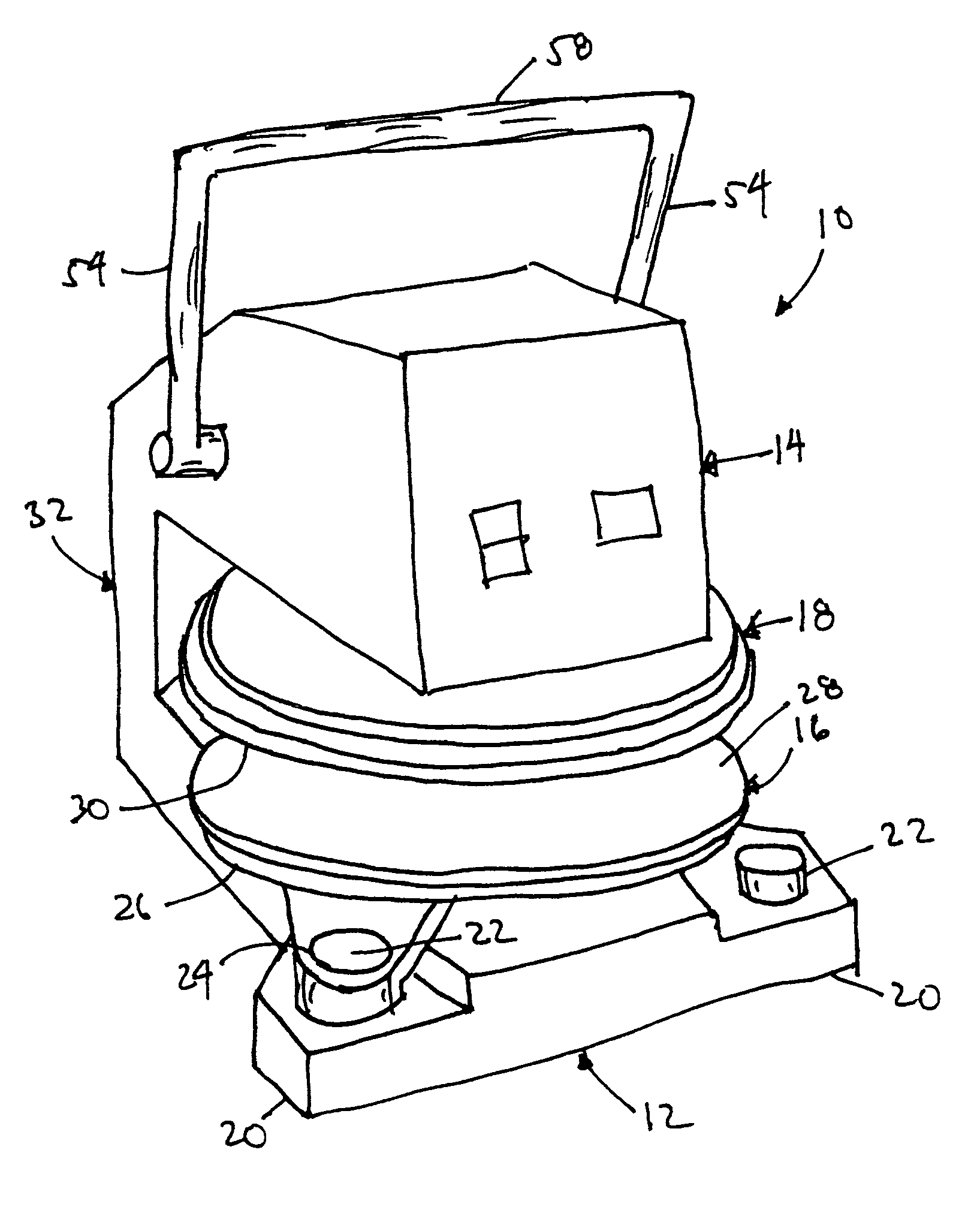
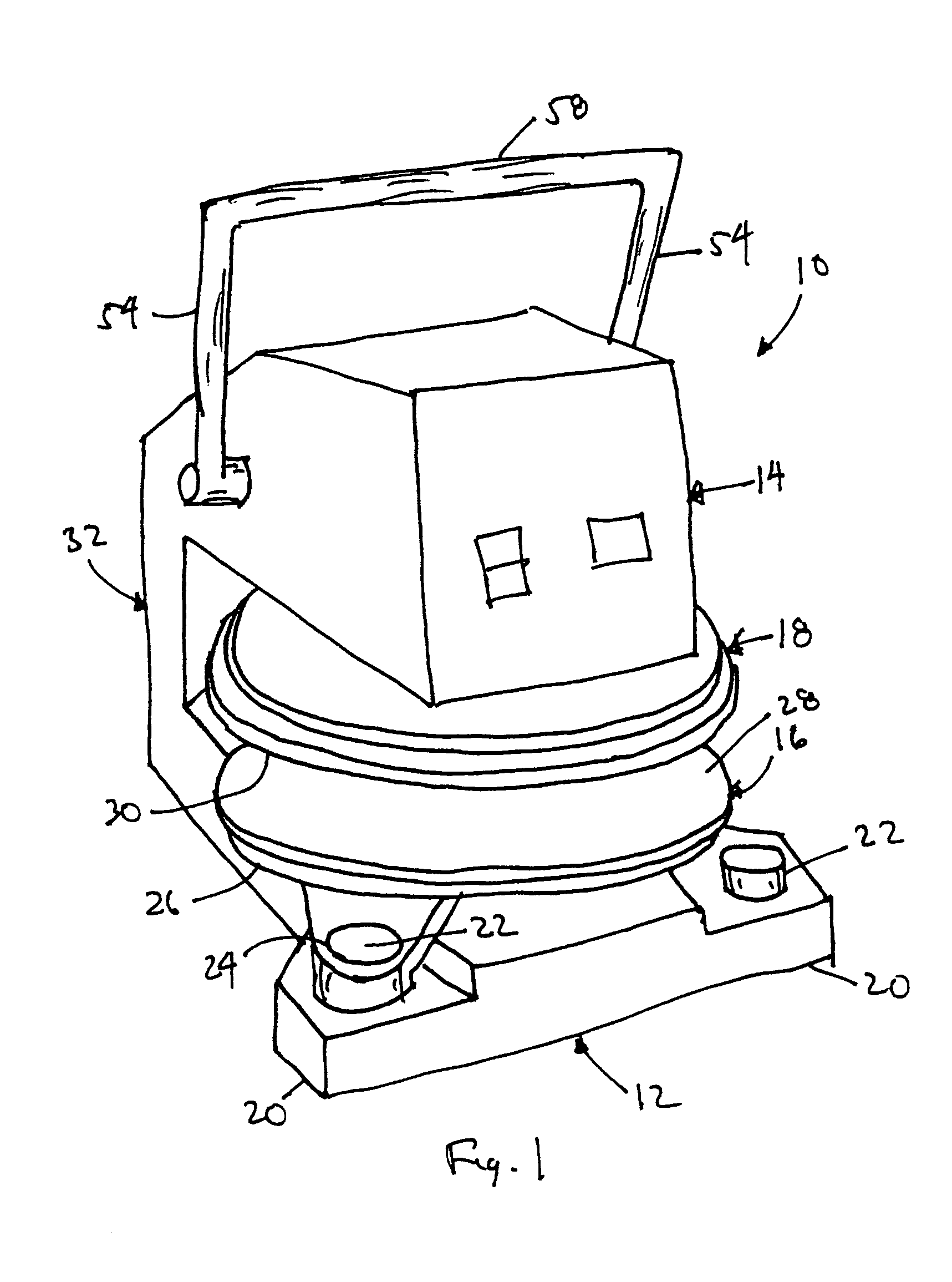
[0041]The dough press 10 of the present invention is shown in the figures. The dough press 10 includes frame 32 that has a base 12 supporting a lower platen 16 and an upper housing 14 supporting an upper platen 18. The platens 16, 18 are supported substantially horizontally and substantially in parallel with each other. The upper housing 14 includes a drive mechanism whereby the upper platen 18 is manually moved toward and away from the lower platen 16. In the open position, the upper platen 18 is spaced from the lower platen 16. In the closed position, dough placed on the lower platen 16 is compressed between the upper platen 18 and lower platen 16.

[0042]Typically, the working surface 30 of the upper platen 18 and the working surface 28 of the lower platen 16, that is, the opposed surfaces that make contact with the dough being worked, are flat. The result after pressing is a flat sheet of dough. The present invention, however, contemplates that the working surfaces 28, 30 may incl...


PUM

PropertyMeasurementUnit
reciprocating movementaaaaaaaaaa
stored mechanical energyaaaaaaaaaa
pressureaaaaaaaaaa

Abstract

A manually operated dough press comprising a frame with a base and a housing, an upper platen having a working surface, and a lower platen attached to the base and having a working surface opposed to, substantially parallel to, and spaced from the upper platen working surface. The upper platen is attached to the lower end of a shaft that extends from the housing and mounted for reciprocating motion. A pair of mated interlocking components, one attached to the shaft and one attached to the housing, provide stability for vertical reciprocation. The drive mechanism includes a rod fixed perpendicularly to the shaft interlocking component, a pair of cam with spiral slots within which the ends of the rod ride, and an axle to which the cams are mounted and driven by a handle that rotates the cams to raise and lower the upper platen. Counterbalance for the upper platen / shaft is provided by a torsion bar assembly.

Description

CROSS-REFERENCES TO RELATED APPLICATIONS[0001]The present application is a continuation-in-part application of application Ser. No. 10 / 236,630, dated Sep. 6, 2002 for DOUGH PRESS in the names of Andrew D. Voyatzakis and George Athanasiadis, now U.S. Pat. No. 6,769,898.STATEMENT REGARDING FEDERALLY SPONSORED RESEARCH OR DEVELOPMENT[0002]Not ApplicableREFERENCE TO A SEQUENCE LISTING, A TABLE, OR A COMPUTER PROGRAM LISTING COMPACT DISK APPENDIX[0003]Not ApplicableBACKGROUND OF THE INVENTION[0004]1. Field of the Invention[0005]The present invention relates to restaurant equipment, more particularly, to manual presses for producing flat sheets of dough.[0006]2. Description of the Related Art[0007]The purpose of a dough press is to flatten a quantity of dough to produce, for example, a pizza crust. A typical manual dough press has two horizontal platens with opposing working surfaces. Normally, the surfaces are flat, except when special shapes are desired, for example, to create a raised ...

Claims


Application Information

Patent Timeline
Patent Type & Authority Patents(United States)
IPC IPC(8): A21C11/00
CPCA21C11/006
Inventor VOYATZAKIS, ANDREW D.ATHANASIADIE, GEORGE
Owner SOMERSET INDS
Learn More