
Grate assembly

a technology of draining system and grate, which is applied in the direction of sewer cleaning, paving gutter/kerb, sewer cleaning, etc., can solve the problems of unsafe grate, unappealing grate, and complicated installation,

Inactive Publication Date: 2005-09-13
BALCO
View PDF31 Cites 55 Cited by
  • Summary
  • Abstract
  • Description
  • Claims
  • Application Information

AI Technical Summary

Benefits of technology

[0011]The drainage system grate assembly of the present invention overcomes the above-identified problems and provides a distinct advance in the art. More particularly, the present invention relates to a drainage system grate assembly including a drainage system grate that can be secured over a drainage system without deforming the grate or causing a tripping hazard.
[0013]Each tread bar spans the watercourse perpendicularly from and is supported by the crossbars. Each tread bar seats in a channel in each crossbar and includes a course upper surface to ensure good traction and prevent a person or vehicle from slipping as they traverse over the watercourse.

Problems solved by technology

Stolen or unseated grates are hazardous, because a removed or unseated grate cannot prevent a person or a vehicle from falling into a drainage system.
There are two main problems with these assemblies.
This complicates the installation and can result in an aesthetically unappealing grate.
Another problem is that the grate bar is typically only affixed to some tread bars.
The stressed tread bars can bend and cause an uneven surface.
The uneven surface is aesthetically unappealing and can present a tripping hazard.
A disadvantage of this construction is that only two tread bars are stressed, which can cause an uneven surface as discussed above.

Method used


Image

  • Grate assembly
  • Grate assembly
  • Grate assembly

Examples


Embodiment Construction

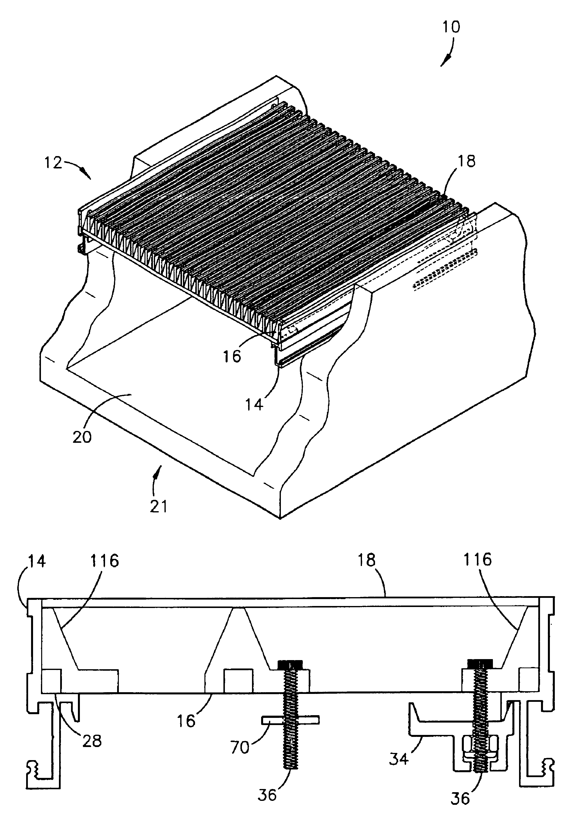
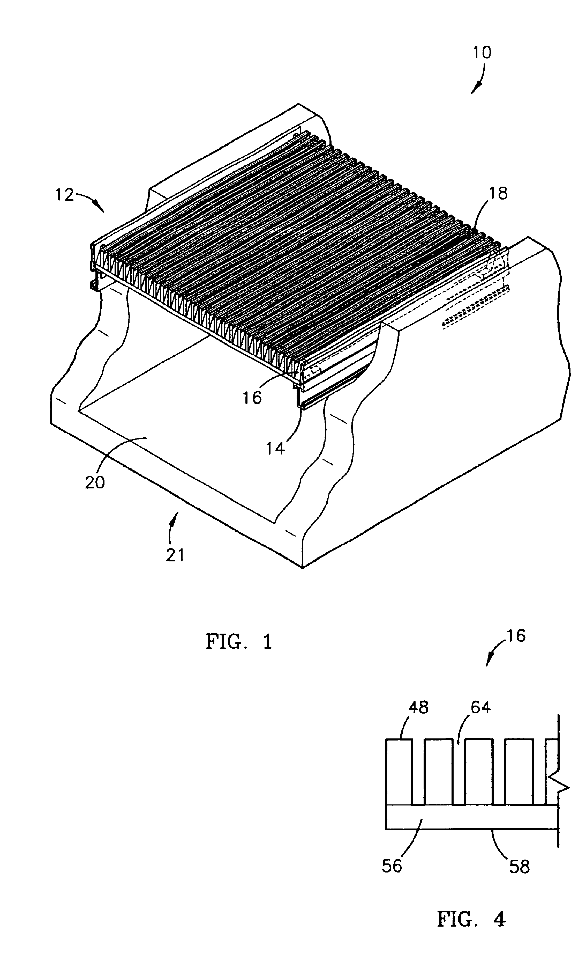
[0027]Referring to FIG. 1, a drainage system grate assembly 10 constructed in accordance with a preferred first embodiment of the invention broadly comprises a grate 12 seated within and supported by a frame 14. The grate 12 comprises two or more crossbars 16 and a plurality of tread bars 18. Each crossbar 16 spans a watercourse 20 of a drainage system 21 and is supported by the frame 14 at both ends.

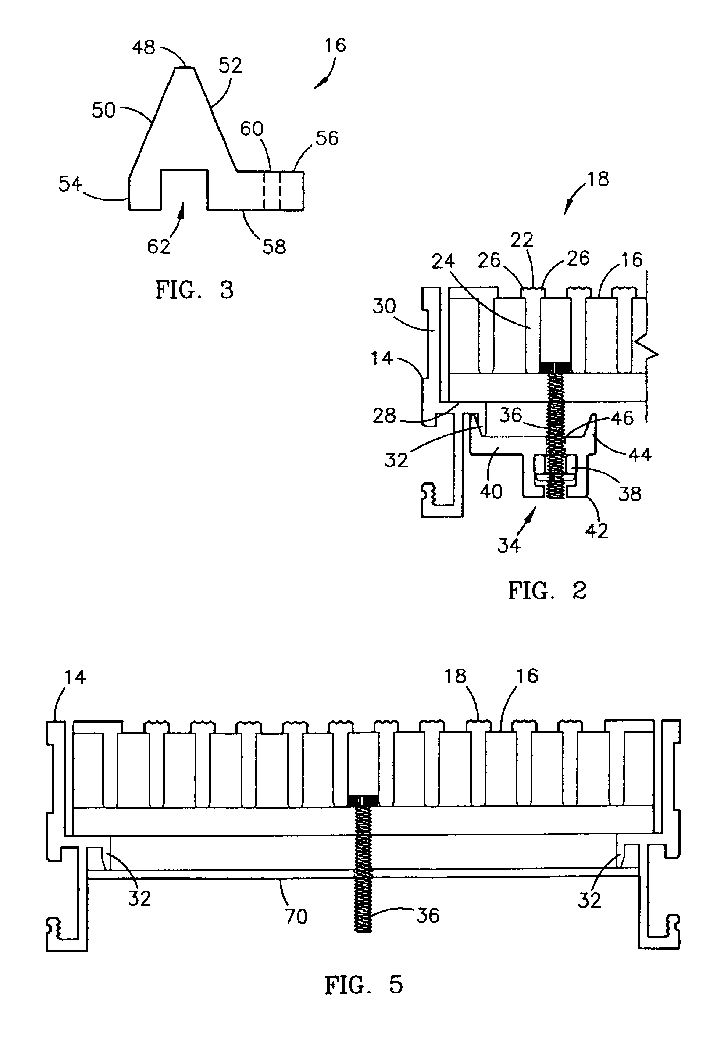
[0028]Also referring to FIG. 2, each tread bar 18 spans the watercourse 20 perpendicularly from and is supported by the crossbars 16. Each tread bar 18 includes a substantially horizontal grip portion 22 and a substantially vertical channel portion 24. The grip portion 22 has a course upper surface to ensure good traction and prevent a person or vehicle from slipping as they traverse over the watercourse 20, and two shoulders 26. Each tread bar 18 is preferably constructed of extruded aluminum but may be formed of any rigid material.

[0029]The frame 14 is typically formed or set into the...


PUM


Abstract

A preferred drainage system grate assembly (10) broadly comprises a grate (12), a frame (14) to support the grate (12), and a locking device (34) to hold the grate (12) within the frame (14). The grate (12) comprises two or more crossbars (16) and a plurality of tread bars (18). Each crossbar (16) spans a watercourse (20) of a drainage system (21) and is supported by the frame (14) at both ends. The crossbar (16) includes an integral flange (56) that protrudes from the crossbar (16) substantially horizontally and at least one hole (60) centered within the flange (56). The locking device (34) includes a penetration (46) where a bolt (36) is inserted through the hole (60). As the bolt (36) is turned, the locking device (34) is raised until it contacts the frame (14), thereby securing the grate (12) within the frame (14).

Description

BACKGROUND OF THE INVENTION[0001]1. Field of the Invention[0002]The present invention relates to drainage system grate assemblies. More particularly, the present invention relates to a drainage system grate assembly including a drainage system grate that can be secured over a drainage system without deforming the grate or causing a tripping hazard.[0003]2. Description of the Prior Art[0004]Drainage system grates are typically comprised of several tread bars and two or more crossbars that drop into frames to cover drainage systems. The frames are typically secured over or within a drainage system, while it is being constructed. The frames not only support the grates, but also provide a convenient platform to which the grates may be secured.[0005]Drainage system grates are typically secured to their frames by grate locking assemblies to prevent theft by vandals or thieves and to ensure that the grates don't become unseated by heavy use. Stolen or unseated grates are hazardous, because...

Claims


Application Information

Patent Timeline
Patent Type & Authority Patents(United States)
IPC IPC(8): E03F5/06
CPCE03F5/06E03F2005/063
Inventor KNAK, RONNY L.BALOCCA, DEAN V.
Owner BALCO
Learn More