
Pneumatic riser release

a technology of pneumatic riser and parachute, which is applied in the direction of fluid-pressure actuators, pyrotechnical actuators, emergency apparatus, etc., can solve the problems of unfavorable unmanned cargo drop, and difficult early mechanical connection use, and achieve the effect of preventing accidental releas

Inactive Publication Date: 2005-09-13
ATAIR AEROSPACE
View PDF5 Cites 10 Cited by
  • Summary
  • Abstract
  • Description
  • Claims
  • Application Information

AI Technical Summary

Problems solved by technology

Early mechanical connections were difficult to use when the webbing was under tension, such as during flight.
While the three ring release is an excellent mechanism for a quick, easily operable release of risers by a parachutist, it is not easily adaptable for use in unmanned cargo drops.
However, there are disadvantages in using a remote linear actuator.
Additionally, even with a hard cable housing, the cable can kink at the point where it contacts the string loop due to forces on the loop, particularly when high weights or g-forces are encountered.
The detent formed at the loop contact point can require a very high actuation force to pull the cable, making a release impossible.
A solid metal pin could solve the detent problem but cannot be used at the end of the cable.
A short pin could result in premature release.
With a short pin any tension could cause the pin to be pulled prematurely.

Method used


Image

  • Pneumatic riser release
  • Pneumatic riser release
  • Pneumatic riser release

Examples


Embodiment Construction

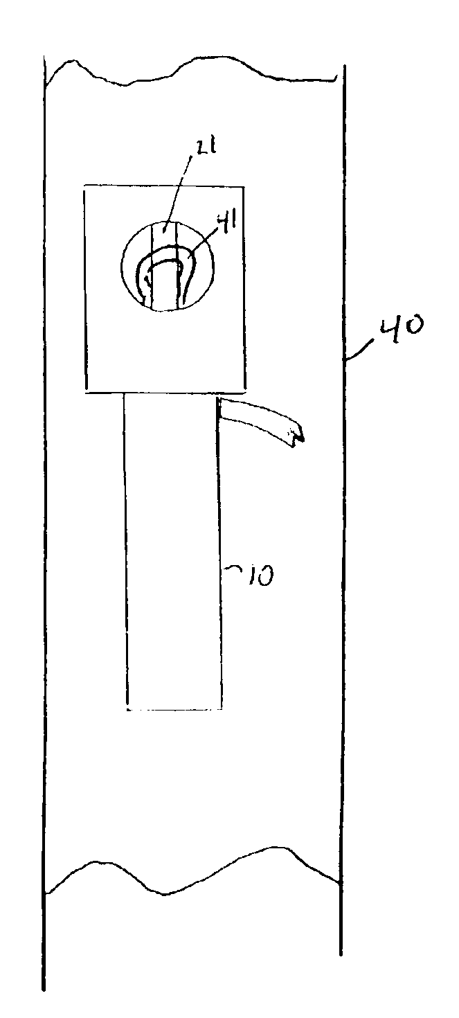
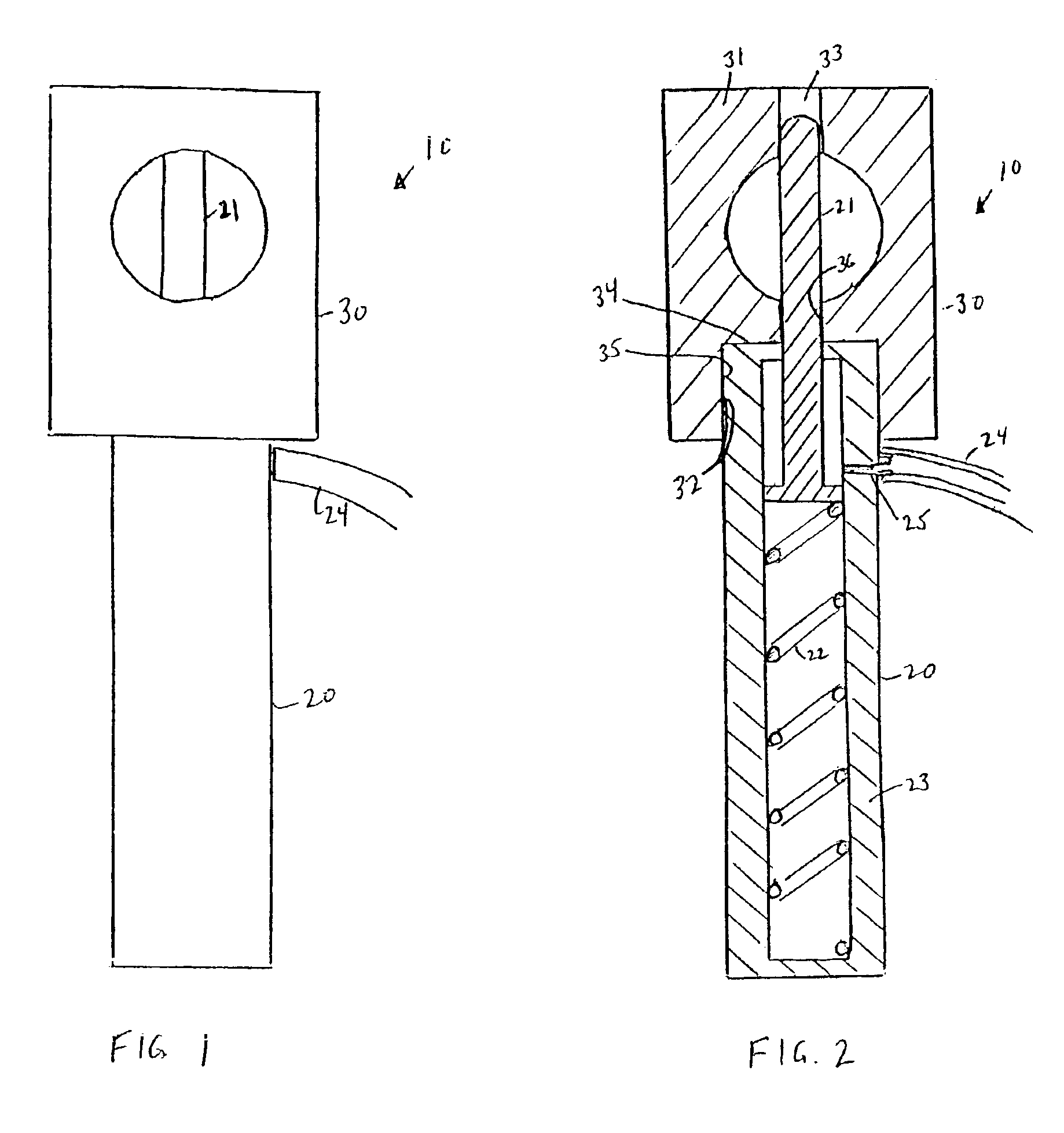
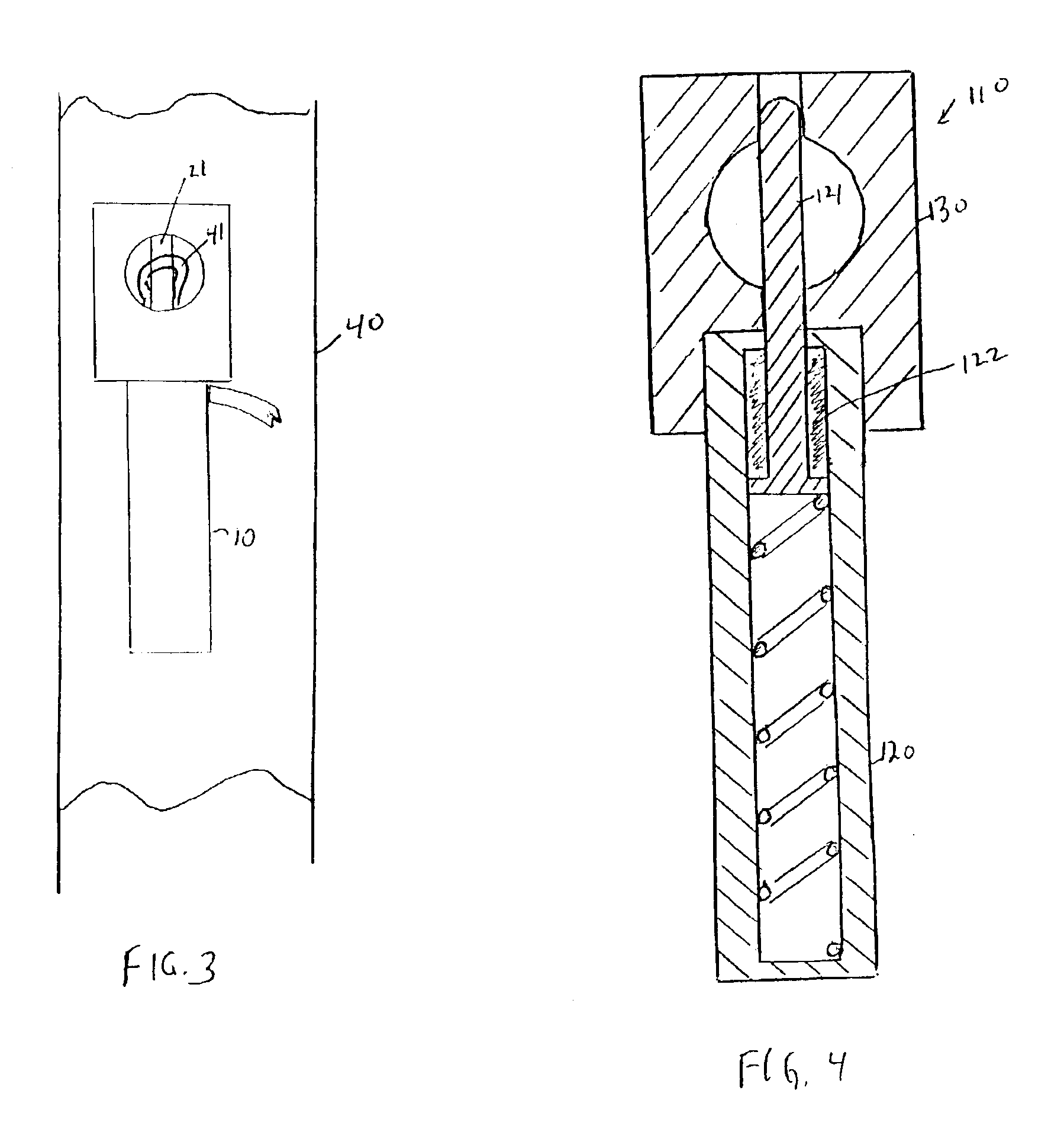
[0015]FIG. 1 illustrates an embodiment of a release control mechanism 10 according to an embodiment of the invention. The release control mechanism 10 includes a pneumatic or hydraulic cylinder 20 and a engagement hole 30. FIG. 2 is a cross sectional view of the release control mechanism 10 which illustrates the relationship between the components. The cylinder 20 includes a hardened pin 21 which extends into the engagement hole 30 when in the extended position. When retracted, the pin 21 is completely disengaged from the engagement hole 30. The pin 21 is held in the extended position by an internal spring 22 within the body 23 of the cylinder 20. The engagement hole 30 includes a metal frame 31, with a first bore 32 and a second bore 33. The first and second bores are coaxially aligned. The first bore 32 includes a shoulder 34 between a first portion 35 of a larger diameter and a second portion 36 of a smaller diameter. The first portion 35 of the first bore 36 is sized to receive ...


PUM


Abstract

An automated quick release mechanism for a three ring release includes a pneumatic or hydraulic cylinder with a hardened metal pin. The pin engages a string loop of the three ring release. An internal spring holds the pin in an extended position. A controller external to the automated quick release mechanism provides a gas or fluid pressure to withdraw the pin and disengage the string loop.

Description

[0001]This application claims priority to U.S. Provisional Application Ser. No. 60 / 378,913, filed May 7, 2002.BACKGROUND OF THE INVENTION[0002]1. Field of the Invention[0003]The present invention relates to release mechanisms for loaded straps. More particularly, it relates to a controllable release for a parachute riser.[0004]2. Discussion of Related Art[0005]In parachute applications, it is desirable to have a quick release to separate the harness from the parachute. Different mechanisms have been used for such a purpose. Originally, a parachutist had to cut the webbing of the risers connecting the parachute to the harness. Early mechanical connections were difficult to use when the webbing was under tension, such as during flight. U.S. Pat. No. 4,337,913, entitled “Means for Releasably Attaching Strands”, incorporated herein by reference, disclosed a novel release mechanism which was easily operable, particularly for webbing under tension.[0006]The release mechanism, commonly cal...

Claims


Application Information

Patent Timeline
Patent Type & Authority Patents(United States)
IPC IPC(8): B64D17/00B64D17/38F15B15/00F15B15/19B64D17/46B64D17/52
CPCB64D17/38B64D17/46B64D17/52F15B15/19
Inventor PRESTON, DANIEL
Owner ATAIR AEROSPACE
Learn More