
Television distribution system for signal substitution

a technology of television distribution system and signal substitution, which is applied in the direction of television system, broadcast services for monitoring/identification/recognition, broadcast information switching/replacement, etc., can solve the problems of cable split, control and test group that are not properly matched, and system, however, requires great expense in providing and maintaining sophisticated receiving stations

Inactive Publication Date: 2005-09-06
INFORMATION RESOURCES
View PDF47 Cites 20 Cited by
  • Summary
  • Abstract
  • Description
  • Claims
  • Application Information

AI Technical Summary

Benefits of technology

[0018]To collect and analyze data in the above situation, the market researchers identify a consumer parameter for the consumers / viewers of the community and associate that parameter with one of the zones. For example, the consumer telephone numbers, with the zone including each number, may be recorded in a market research computer. After running a normal / substitute programming test, a person-on-the-street or telephone survey may be conducted in the community to identify the consumers' phone numbers and their purchase behaviors. When the survey data is analyzed, a stored data file associating phone numbers with zones is used to identify the zone associated with each responding consumer so that statistical analysis of consumer behavior can be completed.

Problems solved by technology

There have, however, been difficulties peculiar to the exposing of the selected group to particular promotional material as well as problems peculiar to measuring their responses.
A particular problem is that the method of exposure of the selected group to the promotional material or the collection of the responses may skew the results; that is, the testing itself may influence the results independently of the material being tested.
A problem that has developed with this is that the split of the cable produces control and test groups that are not properly matched for market testing.
However, even here there is a problem that once the cables are laid the cables themselves select the groups; that is the television viewers are either on cable A or on cable B and do not admit of special selection to meet the needs of a particular market test.
The system, however, requires great expense in providing and maintaining sophisticated receiving stations in each panelist household.

Method used


Image

  • Television distribution system for signal substitution
  • Television distribution system for signal substitution
  • Television distribution system for signal substitution

Examples


Embodiment Construction

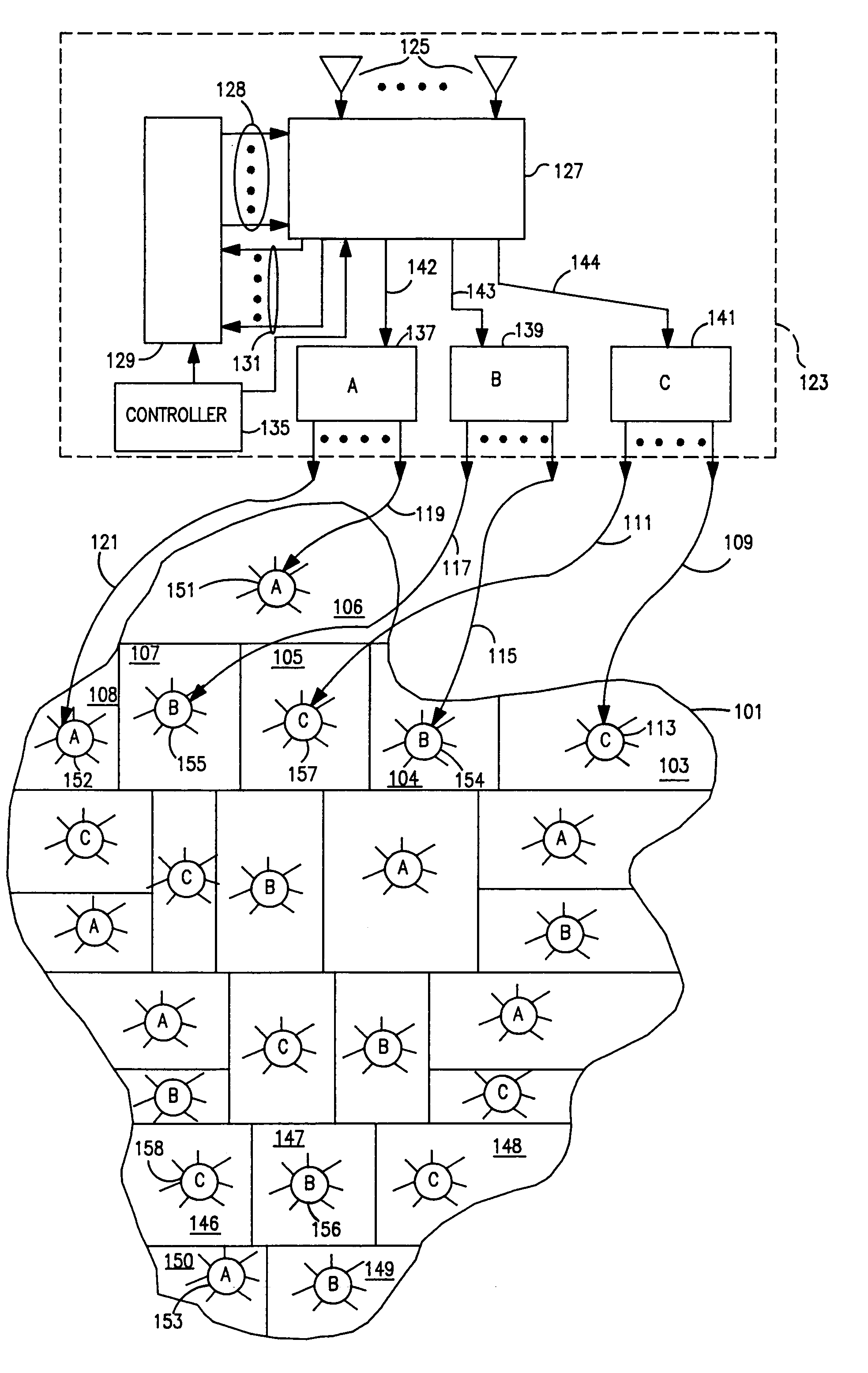
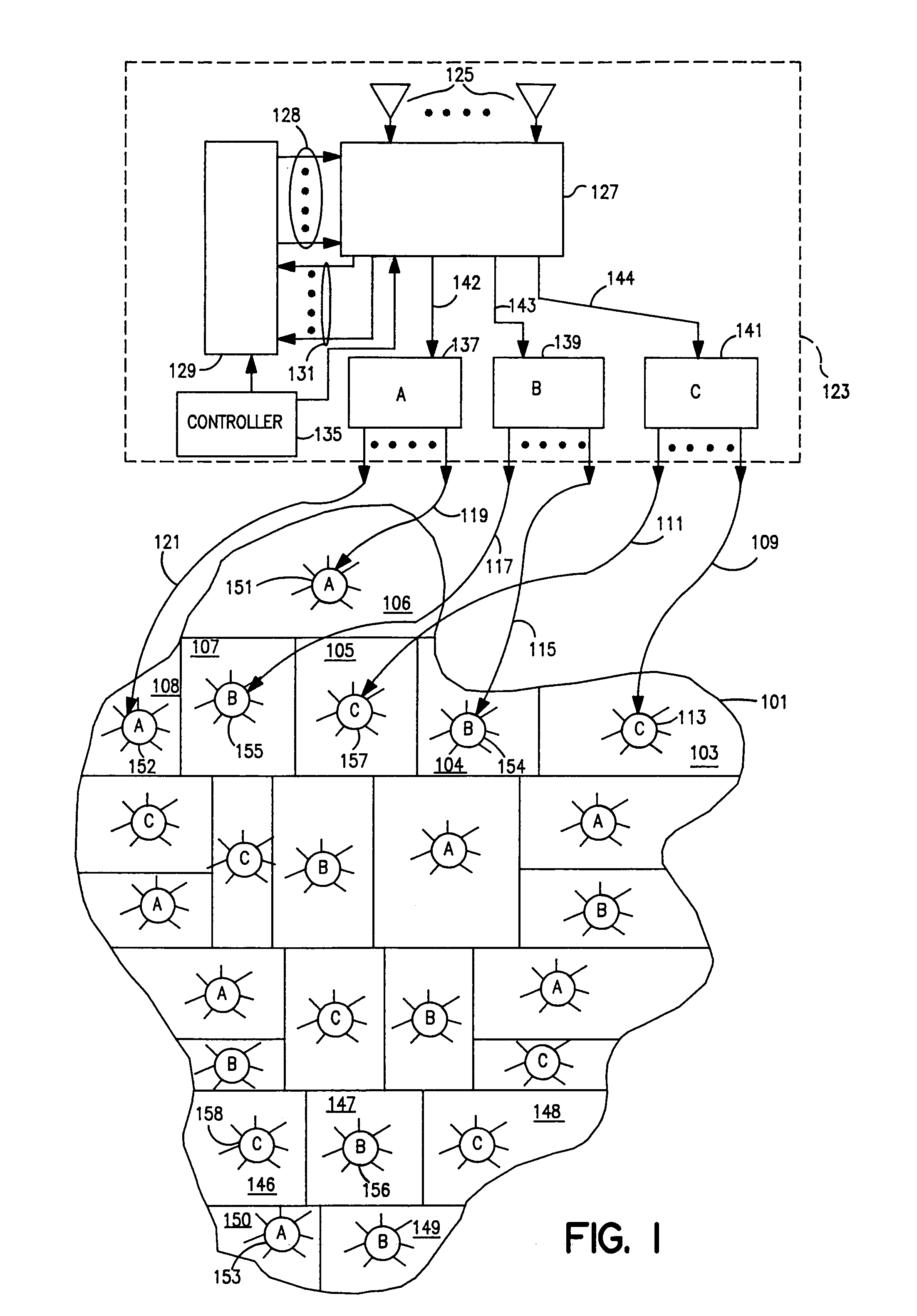
[0027]FIG. 1 is a general block diagram showing a targeted television system in accordance with the present invention for delivering cable television signals to a viewer community represented by irregular area 101. Twenty-four zones, of which only zones 103 through 108 have been numbered, make up the community. Each of the zones represents an area of the community in which the cable television subscribers are served from a single cable feed such as cable feeds 109 and 111. The zones will not be as regular as shown because they are determined by the cable television company based on the economics of providing cable services. Each zone, however, includes a number of geographically proximate subscribers and is referred to herein as being substantially contiguous. Further, it is possible that over time the zone boundaries will change as new subscribers request cable service and other subscribers give up their prior service.

[0028]Each zone, e.g. 103, includes a signal distribution point ...


PUM


Abstract

A cable television distribution system in which the head end substitutes different channels for a plurality of separated geographic zones. The head end creates a plurality of channel spectrums and transmits the spectrums on distribution trunks such that a different spectrum may be present on each distribution trunk. The spectrums on the distribution trunks are connected to zones of the viewer community which have been selected for market research purposes on the basis of demographics. Product sales collection units are provided at stores throughout the community served by the cable television distribution to collect consumer purchase data for market research purposes.

Description

CROSS-REFERENCE TO RELATED APPLICATIONS[0001]This application is a continuation-in-part of U.S. patent application Ser. No. 08 / 693,953, filed Aug. 7, 1996, now abandoned.BACKGROUND OF THE INVENTION[0002]This invention relates generally to the accumulation of consumer response information and more particularly to the presentation of selected information to viewers of targeted television programming and the accumulation of responses from those viewers.[0003]Conventional market research has involved subjecting selected groups of consumers to particular promotional material and observing their responses. There have, however, been difficulties peculiar to the exposing of the selected group to particular promotional material as well as problems peculiar to measuring their responses. A particular problem is that the method of exposure of the selected group to the promotional material or the collection of the responses may skew the results; that is, the testing itself may influence the resu...

Claims


Application Information

Patent Timeline
IPC IPC(8): H04N7/10H04H1/04H04H20/78H04H60/33H04H60/63H04H60/66
CPCH04H20/103H04H60/33H04N7/10H04H20/78H04H60/63H04H60/66
Inventor COWAN, THOMAS M.THOMAS, SCOTT J.RICHARDSON, BRUCE C.
Owner INFORMATION RESOURCES
Learn More