
Measurement controller for vehicle

a technology for measuring controllers and vehicles, applied in the direction of electrical control, navigation instruments, instruments, etc., can solve the problems of not taking into account the differences in time lengths required for signal processing in radar apparatuses and image processing apparatuses

Inactive Publication Date: 2005-09-06
HITACHI LTD
View PDF10 Cites 39 Cited by
  • Summary
  • Abstract
  • Description
  • Claims
  • Application Information

AI Technical Summary

Problems solved by technology

However, in the conventional technique, in the case of controlling the operation of a vehicle by utilizing output signals from the millimeter wave radar apparatus or the light radar apparatus (hereinafter abbreviated as a radar apparatus) and the image processing apparatus, it has not been taken into consideration that time lengths required for signal processings in the radar apparatus and the image processing apparatus differ depending on scenes.
Thus, there arises a problem that this time difference appears as a control error in the vehicle control since such a time difference has not been taken into consideration.

Method used


Image

  • Measurement controller for vehicle
  • Measurement controller for vehicle
  • Measurement controller for vehicle

Examples


Embodiment Construction

[0037]Hereinafter, an embodiment of the present invention will be explained with reference to FIGS. 1 to 9.

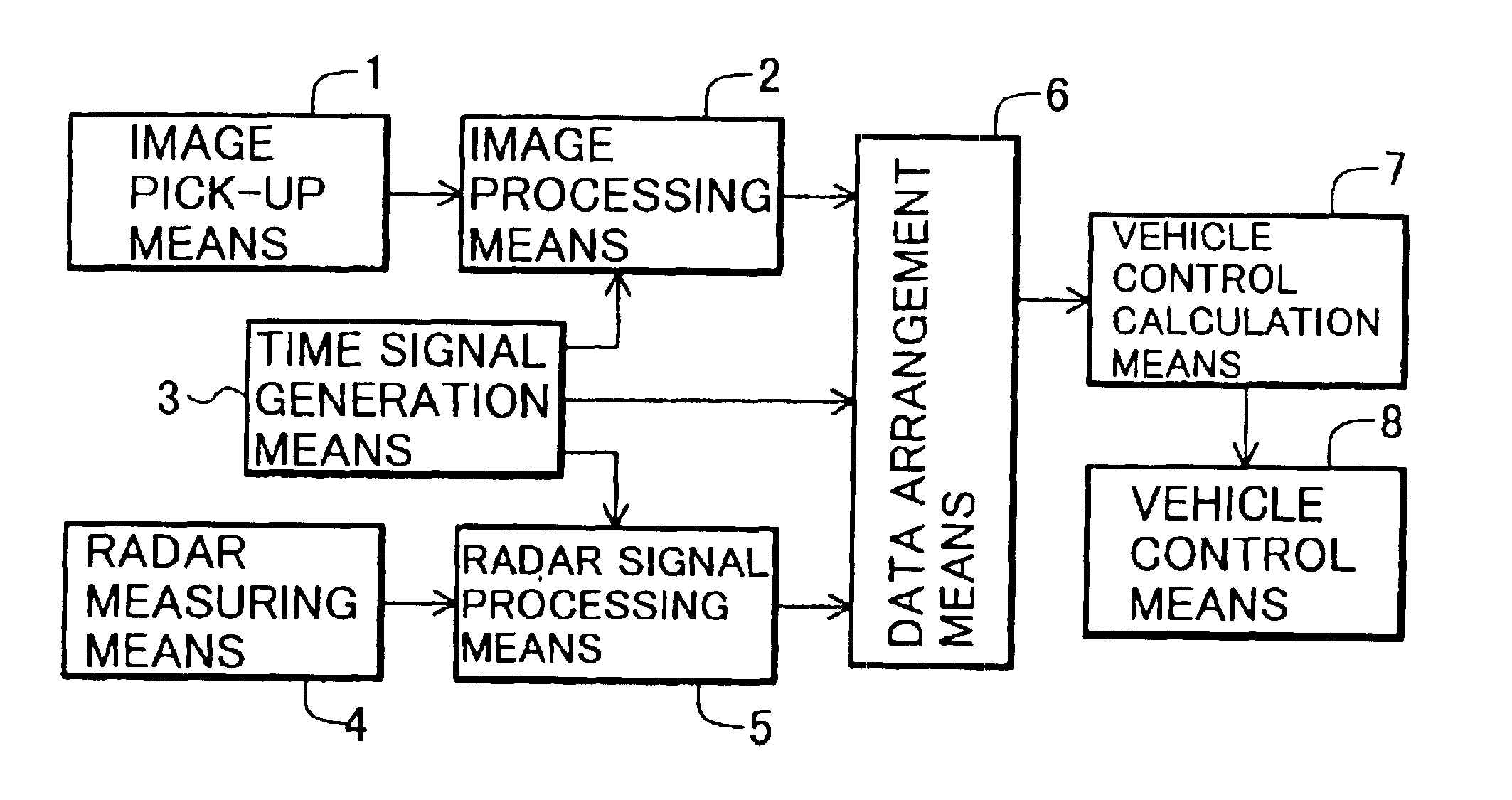
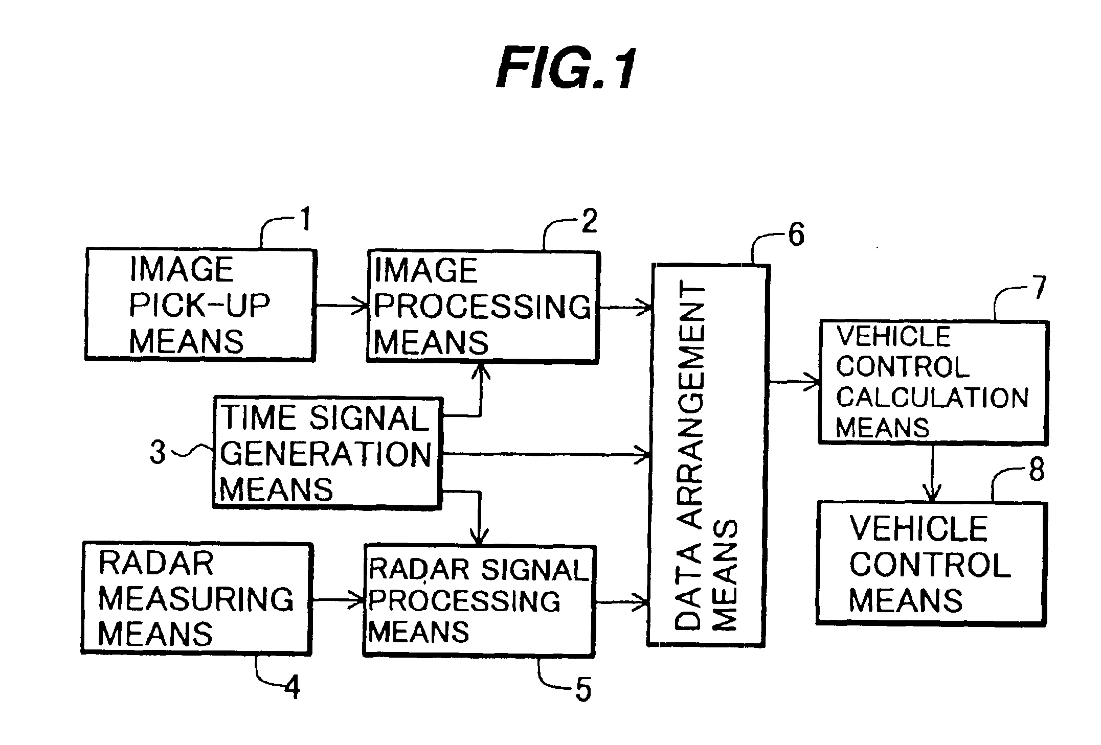
[0038]FIG. 1 is a system diagram of a measuring and controlling apparatus for a vehicle according to the embodiment of the present invention. The measuring and controlling apparatus for a vehicle includes an image pick-up means 1, an image processing means 2, a time signal generation means 3, a radar measuring means 4, a radar signal processing means 5, a data arrangement means 6, a vehicle control calculation means 7 and a vehicle control means

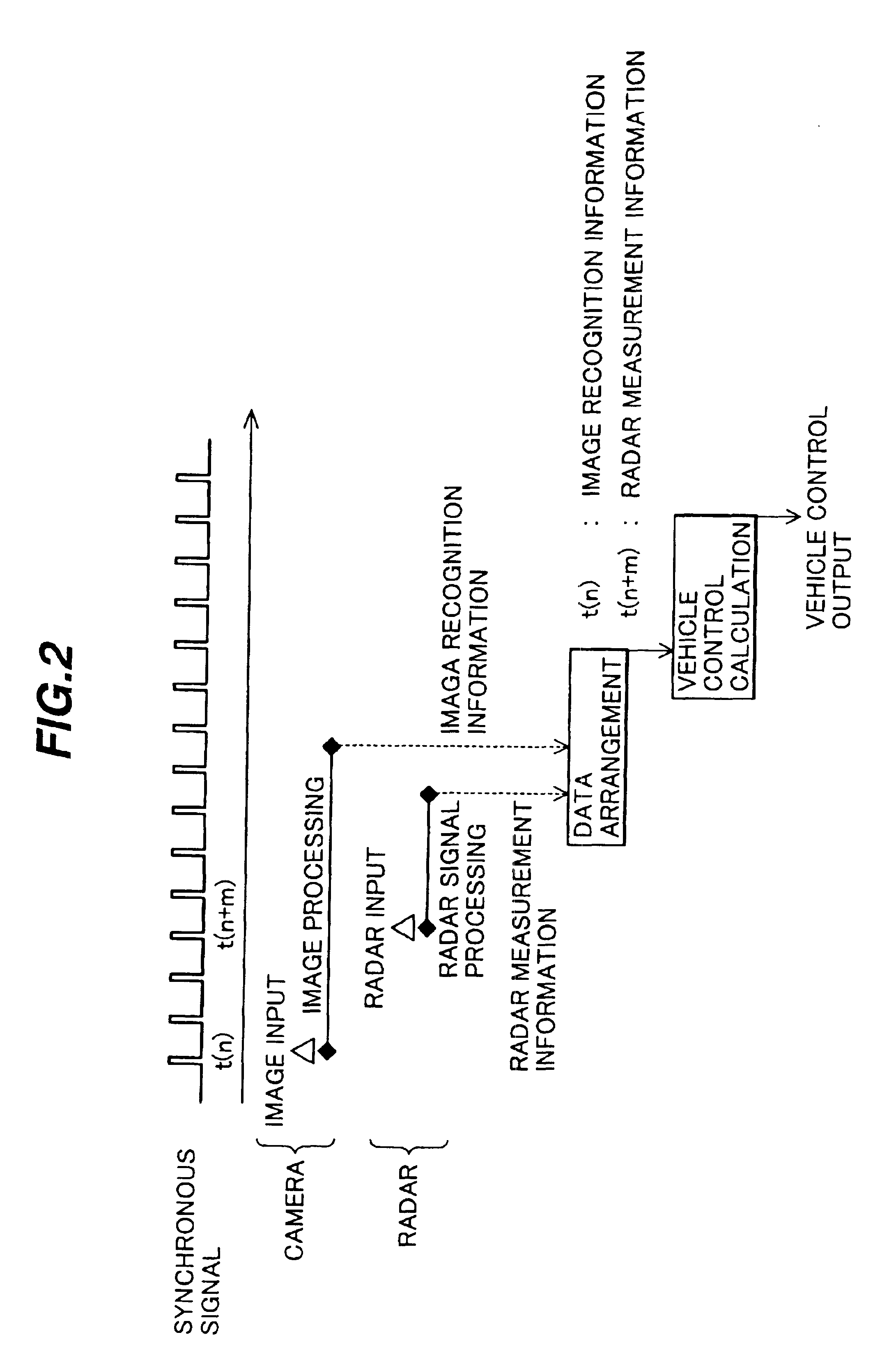
[0039]An example of operations of these respective means 1 to 8 will be explained with reference to a timing chart shown in FIG. 2.

[0040]In FIG. 2, the image pick-up means (camera) 1 photographs or picks up an image of a status ahead of an own vehicle and sends information thus photographed to the image processing means 2. The image processing means 2 records an image input timing at which the mage is photographed in the form of a time s...


PUM


Abstract

A measuring and controlling apparatus for a vehicle includes an image processing device, which is mounted on a vehicle, photographs a circumferential state of the vehicle and processes the image signal; a radar signal processing device, which radiates radio wave or light to process a receiving signal; and a control device for controlling a brake, a throttle valve or a transmission based on the output results of the image processing device and the radar signal processing device. In such a measuring and controlling apparatus for a vehicle, the respective output information of the image processing device and the radar signal processing device includes time information at the time of photographing and time information at the time of measuring and the order of the photographed time and the measured time are adjusted. Thus, even if the processing time differs between the cases where a subject to be photographed is simple and complicated, since the photographed time and the measured time can be identified, the suitable processing according to the processing time can be executed. Thus, the running state of the vehicle can be controlled with high accuracy.

Description

TECHNICAL FIELD[0001]The present invention relates to a measuring and controlling apparatus for a vehicle which measures a circumferential state of an automobile and controls the running of the automobile based on the measured result.BACKGROUND OF THE INVENTION[0002]Conventionally, some of measuring and controlling apparatuses for vehicles employ a method of radiating radio wave or light and measuring a distance to a target such as an automobile or obstacle ahead of the automobile and a relative speed with respect to the target.[0003]As a radar apparatus utilizing radio wave, various kinds of millimeter wave radars are described in “Trend of Development of Millimeter Wave Radar for Vehicle”, The Journal of the institute of Electronics. Information and Communication Engineers, 1996, October, pp. 977-981, for example.[0004]An example of radar apparatuses utilizing light is described in JP-A-8-261753.[0005]Further, such a technique is proposed that a camera is mounted on a vehicle, the...

Claims


Application Information

Patent Timeline
Patent Type & Authority Patents(United States)
IPC IPC(8): B60K31/00G01S13/34G01S13/00G01S13/86G08G1/16G01S13/93G01S13/58B60R21/00B60T7/12B60W10/00B60W10/04B60W10/06B60W10/10B60W10/18B60W10/184F02D9/02F02D29/02F02D41/04G01S13/931
CPCB60W10/06B60W10/10B60W10/184B60W30/16G01S13/345G08G1/16G01S13/867G01S13/584G01S13/931G01S2013/9346G01S2013/9367G01S2013/9321G01S2013/9325G01S2013/935G01S2013/9353G01S2013/9319G01S2013/93185G01S2013/9323G01S2013/932
Inventor KURODA, HIROSHITAKENAGA, HIROSHIMORIZANE, HIROTOIZUMI, SHIHO
Owner HITACHI LTD
Learn More