Electrical insulator having a dielectric rod with a slot for receiving an optical fiber cable

a dielectric rod and optical fiber cable technology, applied in the field of electric insulators, can solve the problem of inutility of protective tubes, and achieve the effect of improving the reliability of electrical insulation of electrical insulators

Active Publication Date: 2005-09-06
DRAKA COMTEQ BV
View PDF17 Cites 0 Cited by
  • Summary
  • Abstract
  • Description
  • Claims
  • Application Information

AI Technical Summary

Benefits of technology

The invention is an electrical insulator that includes a dielectric rod with a slot for an optical fiber cable, a covering that surrounds the rod and presents outwardly-directed projections in the form of skirts, and a one-piece covering that comes directly into contact with the rod. The covering skirts are flexible, and the space between the rod and the cable is filled with dielectric material to hold the cable without stress. The invention improves the reliability of electrical insulation and the quality of protection afforded to the optical fiber cable without significantly degrading the quality of protection. The one-piece covering also reduces the number of interfaces between elements and interfaces.

Problems solved by technology

Once the skirts of the covering are glued to the dielectric rod, it has been found that they exert moderate pressure on the dielectric rod, on the filler material, and on the optical fiber cable, and thus that the protective tube is not useful.

Method used


Image

  • Electrical insulator having a dielectric rod with a slot for receiving an optical fiber cable
  • Electrical insulator having a dielectric rod with a slot for receiving an optical fiber cable
  • Electrical insulator having a dielectric rod with a slot for receiving an optical fiber cable

Examples


third embodiment

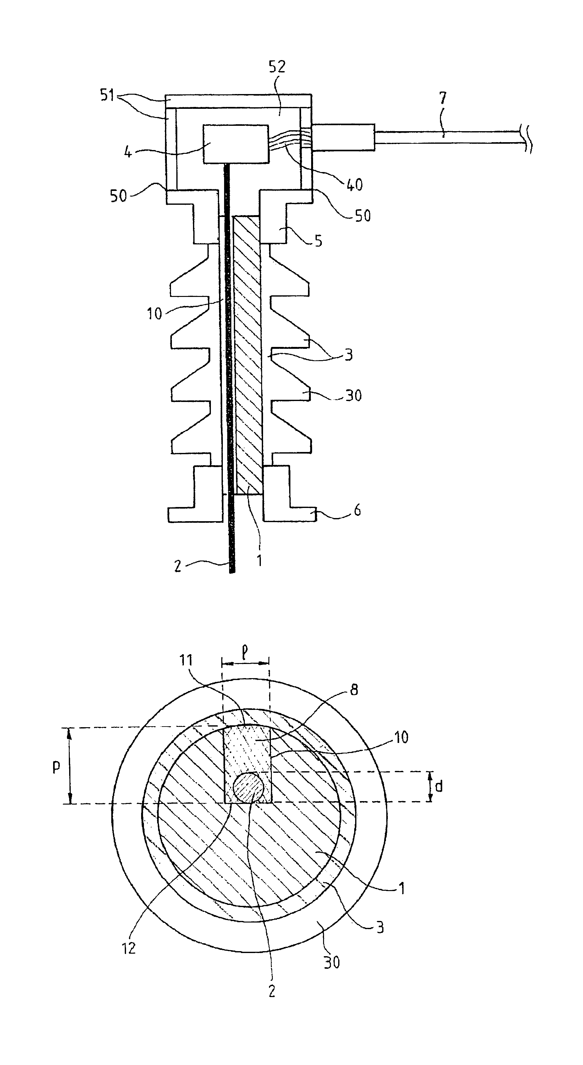
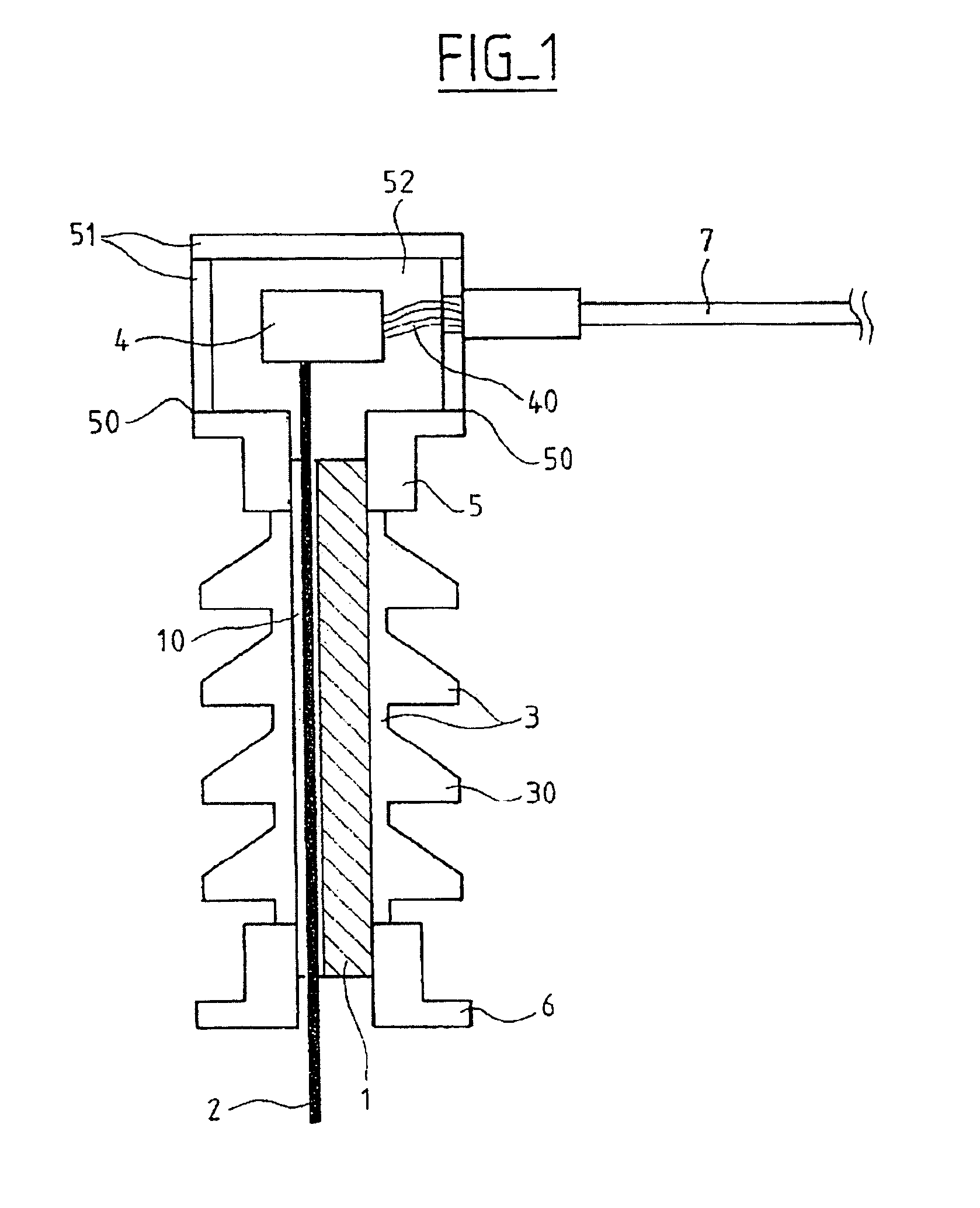
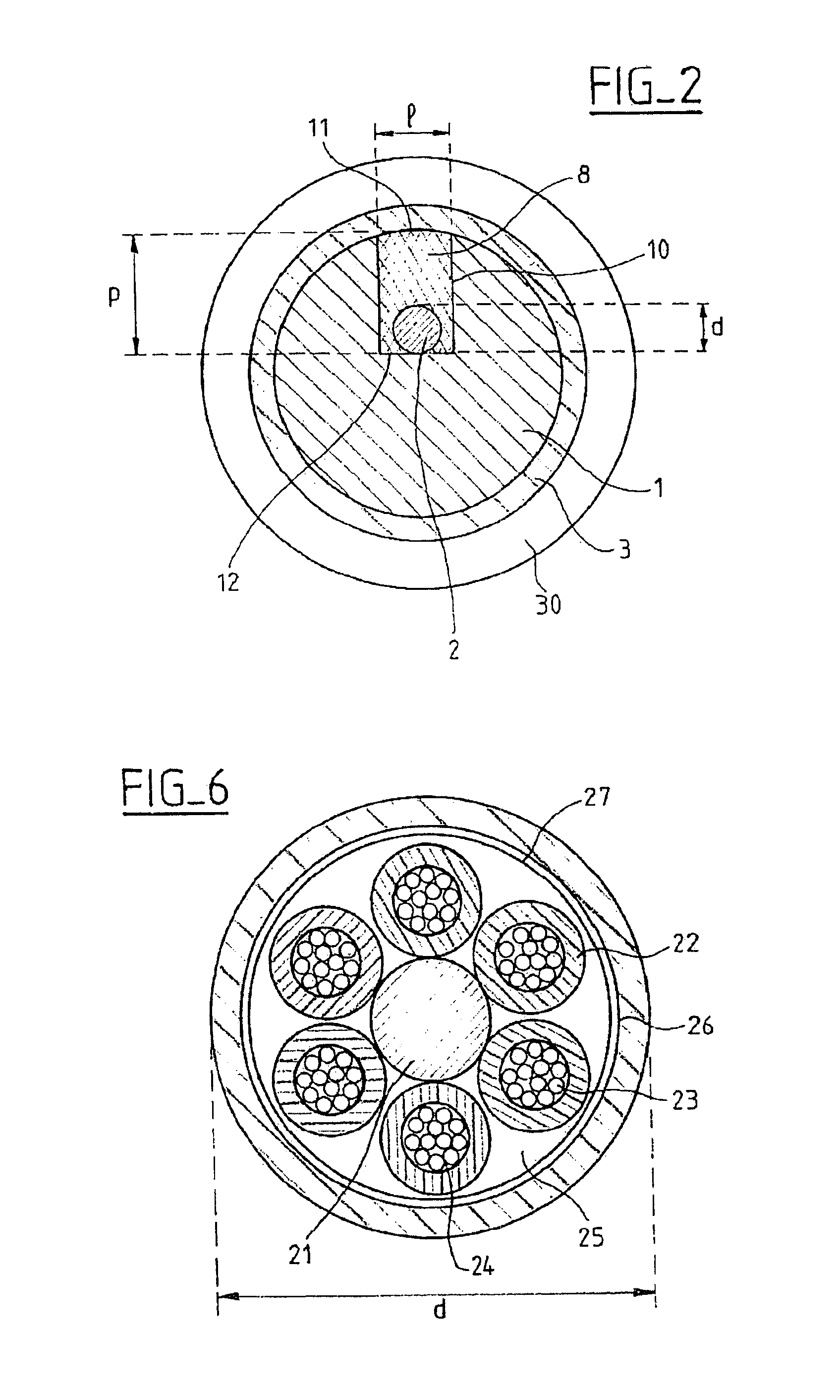
[0017]FIG. 1 is a diagrammatic profile view of a preferred, third embodiment of an electrical insulator of the invention. The electrical insulator comprises a dielectric rod 1. The rod 1 is made of glass fiber, for example. The rod 1 is typically cylindrical in shape. The rod 1 includes at least one slot 10 which extends along the entire length of the rod 1. In the slot 10 there is situated an optical fiber cable 2. All of the space situated within the slot 10 between the rod 1 and the cable 2 is filled with a dielectric filler material for filling the slot 10 and for maintaining the cable 2 in the slot 10 without stressing it; said material is described in greater detail with reference to FIG. 2.

[0018]A covering 3 surrounds the rod 1. On the outside, the covering 3 presents projections 30 in the form of skirts. The covering 3 is typically made of a composite material, e.g. of silicone or of ethylene propylene diene monomer (EPDM) or any other synthetic material. The covering 3 cons...

first embodiment

[0026]FIG. 4 is a diagrammatic longitudinal section view of an electrical insulator of the invention on a scale larger than FIG. 1. The covering 3 is constituted by a stack of skirts 30 that are stuck to one another by an adhesive 32. The skirts are also stuck to the rod 1 by an adhesive 31 which may be identical to the adhesive 32 or different therefrom.

second embodiment

[0027]FIG. 5 is a diagrammatic longitudinal section view of an electrical insulator of the invention, shown on a scale larger than that of FIG. 1. The covering 3 is constituted by a stack of skirts 30 stuck to one another by an adhesive 32. The skirts 30 are also stuck to an intermediate tube 34 by means of an adhesive 33 which is identical to the adhesive 32 or different therefrom. The intermediate tube 34 is in turn stuck to the rod 1 by an adhesive 31 which is identical to the adhesive 32 and 33 or different therefrom. The intermediate tube 34 is situated between the rod 1 and the covering 3 constituted by the skirts 30 stacked and stuck one on another. The intermediate tube 34 and the covering 3 are preferably made of the same material so as to make them easier to stick together.

[0028]FIG. 6 is a diagrammatic cross-section view of a preferred embodiment of the cable 2 situated in the slot 10 in the rod 1 of an electrical insulator of the invention. The optical fiber cable 2 is a...


PUM

PropertyMeasurementUnit
depthaaaaaaaaaa
diameteraaaaaaaaaa
lengthaaaaaaaaaa

Abstract

The invention relates to the field of electrical insulators, and in particular to the field of electrical insulators for optical phase conductors (OPPCs). The electrical insulator comprises a dielectric rod (1) having at least one slot (10), a flexible optical fiber cable (2) situated in the slot (10), a dielectric material (8) filling the slot (10) and holding the cable (2) in the slot (10) without stressing it, and a dielectric covering (3) surrounding the rod (1) and presenting outwardly-directed projections (30) in the form of skirts, the entire space situated between the rod (1) and the cable (2) being filled with said dielectric filler and holding material (8).

Description

BACKGROUND OF THE INVENTION[0001]The invention relates to the field of electrical insulators, and in particular to the field of electrical insulators for power cables known as optical phase conductors (OPPCs). The invention also relates to the field of systems associating an electrical insulator with at least one phase conductor. This type of electrical insulator serves to pass an optical signal from one end to the other of said electrical insulator while providing electrical insulation between the ends of said electrical insulator. This type of electrical insulator serves in particular to make an optical connection between the phase conductors of the overhead electricity network and the underground optical network. Because of the great voltage difference between the overhead electricity network and the underground optical network, electrical insulation needs to be particularly good and reliable. Electrical insulators are conventionally placed at the tops of pylons supporting phase ...

Claims


Application Information

Patent Timeline
Patent Type & Authority Patents(United States)
IPC IPC(8): G02B6/44H01B17/00H01B17/32H01B3/30
CPCG02B6/442H01B3/305H01B17/005H01B17/325
Inventor BONICEL, JEAN-PIERRELE GAC, RENAUD
Owner DRAKA COMTEQ BV
Why Eureka
Try Eureka