
Connector, molding method therefor and molding apparatus therefor

a technology of connector housing and molding method, which is applied in the manufacture of contact member cases/bases, coupling device connections, coupling contact members, etc., can solve the problems of insufficient and achieve the effect of reducing the strength of the housing, increasing the strength of the base and a locking force of the terminal fitting

Active Publication Date: 2005-09-06
SUMITOMO WIRING SYST LTD
View PDF4 Cites 8 Cited by
  • Summary
  • Abstract
  • Description
  • Claims
  • Application Information

AI Technical Summary

Benefits of technology

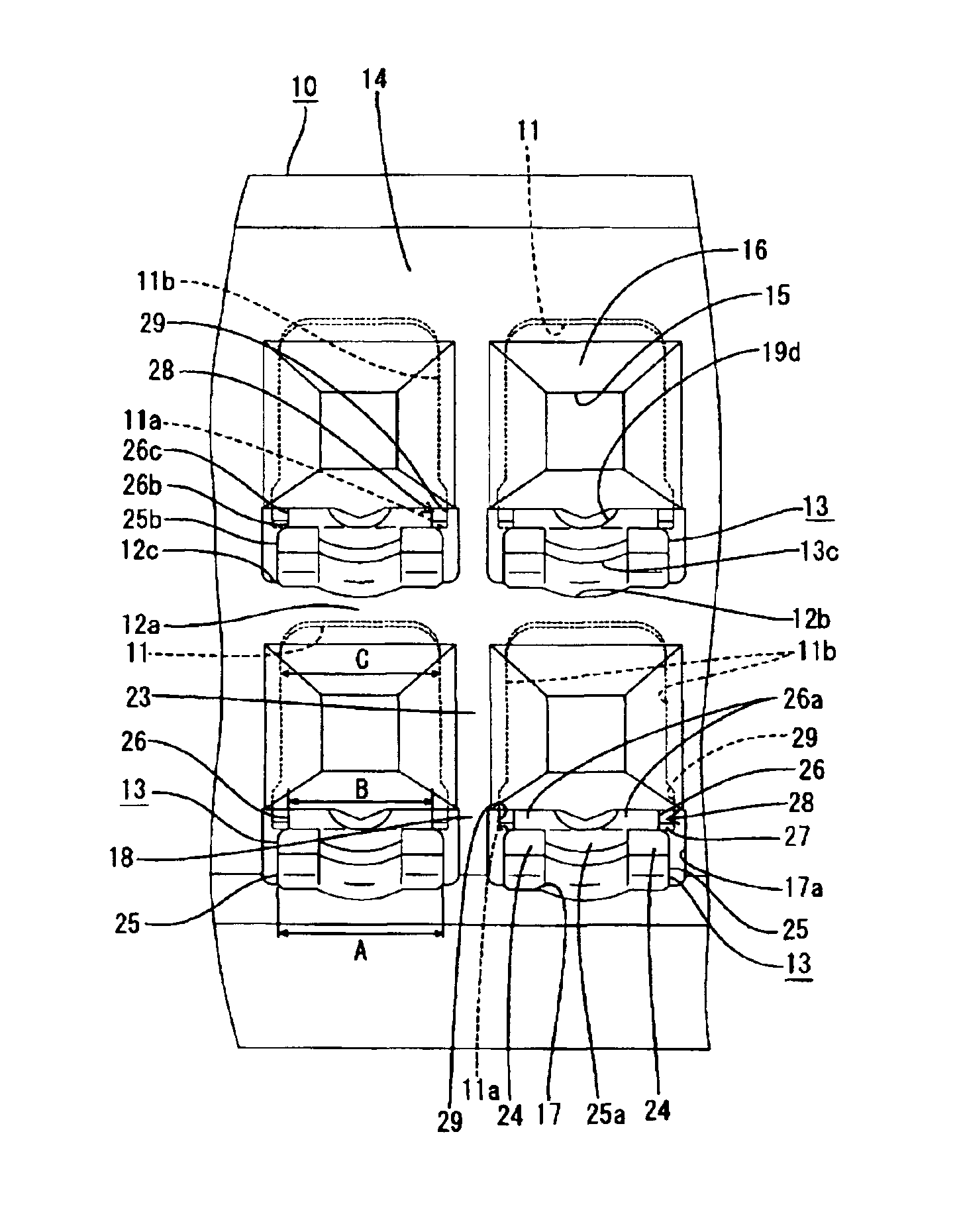
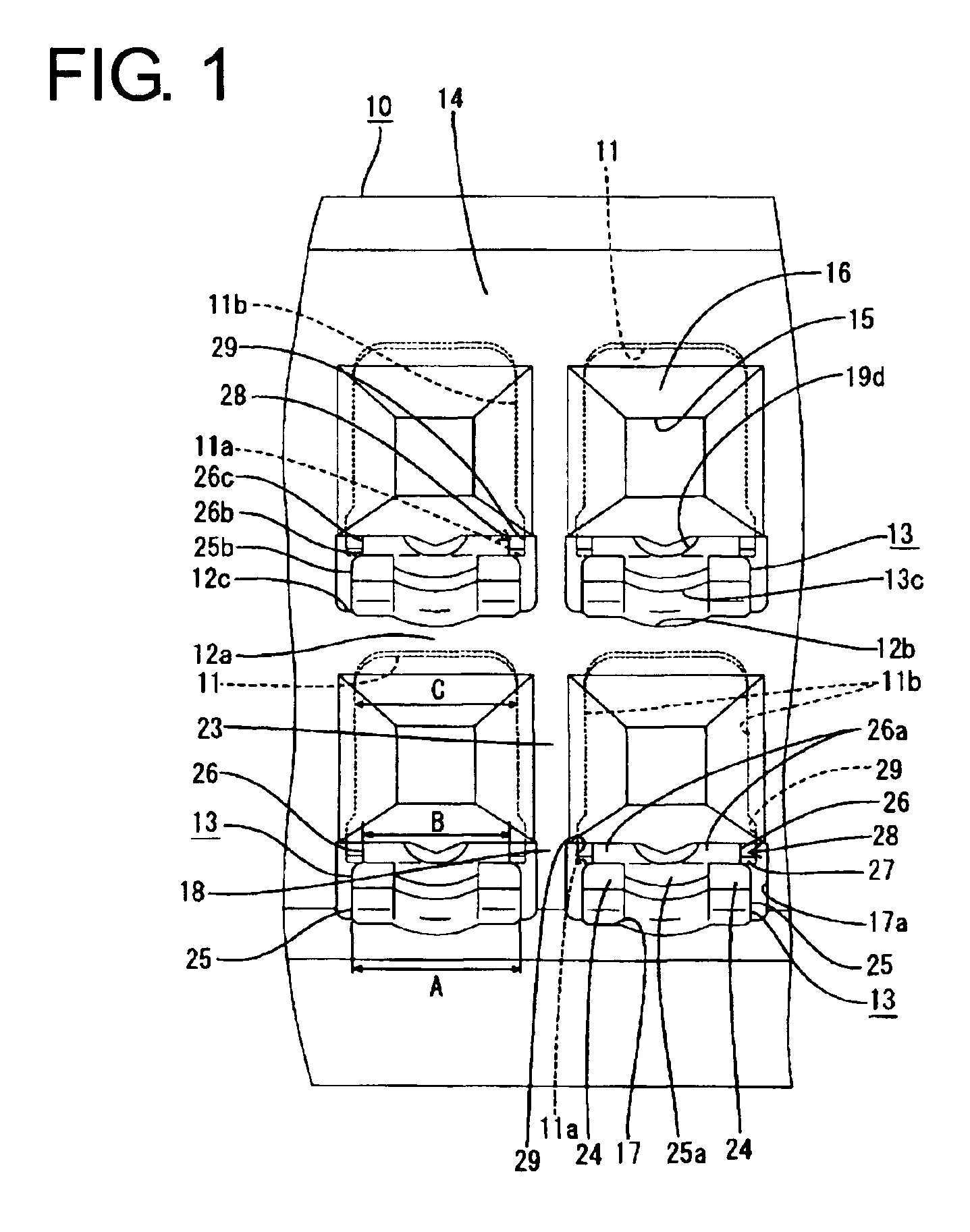
[0008]The width of the base preferably is larger by the width of the notch. As a result, the strength of the base and a locking force for the terminal fitting are increased. The notch is only in an area of the housing before the base of the lock, and has only a small length area as compared to the entire housing. Thus, the notch does not significantly reduce the strength of the housing.
[0009]If the projection had the same width as the base, then a rearwardly open notch would be formed in the inner surface of the cavity by a mold that is moved backward to open. The length of this rearwardly open notch would be larger than the forward-opening notch, and the strength of the housing could be reduced. Accordingly, the projection is narrower than the base in the present invention. Therefore, it is not necessary to form the backward-opening notch or even if such an opening is formed, it can have a smaller width than the forward-opening notch. As a result, the housing is strong.
[0011]The maneuverable portion is wide and thus a section of the maneuverable portion into which the jig is insertable can be wider. Thus, the operability of the lock by the jig is improved and the strength of the jig is enhanced.

Problems solved by technology

Thus, forces for locking the terminal fittings may be insufficient.

Method used


Image

  • Connector, molding method therefor and molding apparatus therefor
  • Connector, molding method therefor and molding apparatus therefor
  • Connector, molding method therefor and molding apparatus therefor

Examples


Embodiment Construction

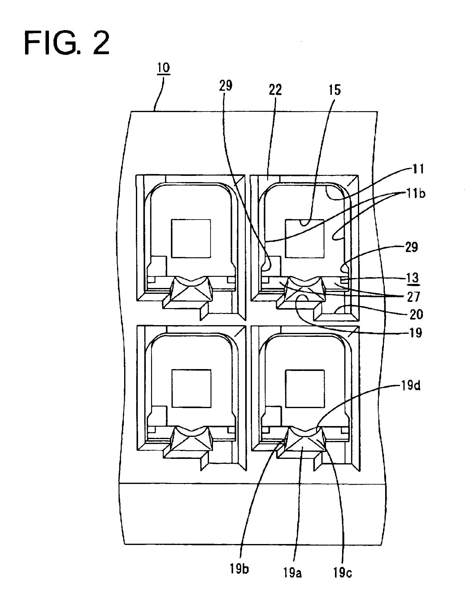
[0033]A female connector according to a preferred embodiment of the invention is described with reference to FIGS. 1 to 15. The female connector includes a female housing 10 into which female terminal fittings 30 are inserted. Each female terminal fitting 30 is electrically connectable with a male terminal fitting (not shown) accommodated in a male housing (not shown) that is fit into the female housing 10. In the following description, an inserting direction ID of the female terminal fitting 30 into the female housing 10 is referred to as a forward direction, a withdrawing direction of the female terminal fitting 30 from the female housing 10 is referred to as a backward direction, and reference is made to all the drawings except FIGS. 5 and 10 concerning vertical direction.

[0034]Each female terminal fitting 30 is formed into a desired shape by embossing, folding and / or bending a conductive metal piece of a specified shape stamped or cut out from a conductive metallic base material...


PUM


Abstract

A connector has a housing (10) with a cavity (11) and a resiliently deformable lock (13) for locking a female terminal fitting (30) in the cavity (11). The lock (13) has a base (25) and a projection (26) that projects into the cavity (11) from the base (25). Both side surfaces (25b) of the base (25) are formed by a mold that is moved forward to open, and notches (17a) are formed in the front surface of the female housing (10) by this mold. The notches (17a) extend more outward than inner side surfaces (11b) of the cavity (11) with respect to the widthwise direction. Both side surfaces (26c) of the projection (26) are formed by a mold moved backward to open. The projection (26) is narrower than the base (25).

Description

BACKGROUND OF THE INVENTION[0001]1. Field of the Invention[0002]The invention relates to a connector and to a method for molding a connector housing.[0003]2. Description of the Related Art[0004]U.S. Pat. No. 5,235,743 discloses a connector that has a housing formed with cavities and resilient locks that project from inner surfaces of the cavities. Terminal fittings are insertable into the cavities of the housing and are locked by the resilient locks to prevent the terminal fittings from coming out of the cavities.[0005]A recent demand to miniaturize connectors has led to smaller cavities, smaller locks and smaller terminal fittings. Thus, forces for locking the terminal fittings may be insufficient.[0006]The present invention was developed in view of the above problem and an object thereof is to allow a connector to be suitably miniaturized.SUMMARY OF THE INVENTION[0007]The invention relates to a connector with a housing. At least one cavity is formed in the housing and a resilientl...

Claims


Application Information

Patent Timeline
IPC IPC(8): H01R43/18H01R43/20H01R13/422H01R13/187H01R13/15H01R43/22H01R13/42
CPCH01R13/4223H01R43/18H01R43/22H01R13/114
Inventor FUKATSU, YUKIHIROSAKURAI, TOSHIKAZU
Owner SUMITOMO WIRING SYST LTD
Learn More