
Advanced patch panel

a patch panel and patch technology, applied in the field of patch panels, can solve the problems of high cross-talk, low telecommunication quality, inconvenient arrangement of network cables, etc., and achieve the effects of reducing the effect of cross-talk, reducing the length difference of network wires, and improving communication quality

Inactive Publication Date: 2005-09-06
HSING CHAU INDAL
View PDF5 Cites 2 Cited by
  • Summary
  • Abstract
  • Description
  • Claims
  • Application Information

AI Technical Summary

Benefits of technology

The solution enables efficient arrangement of network cables from various directions and reduces cross-talk, enhancing telecommunication quality by minimizing length differences between network wires embedded in IDC sets.

Problems solved by technology

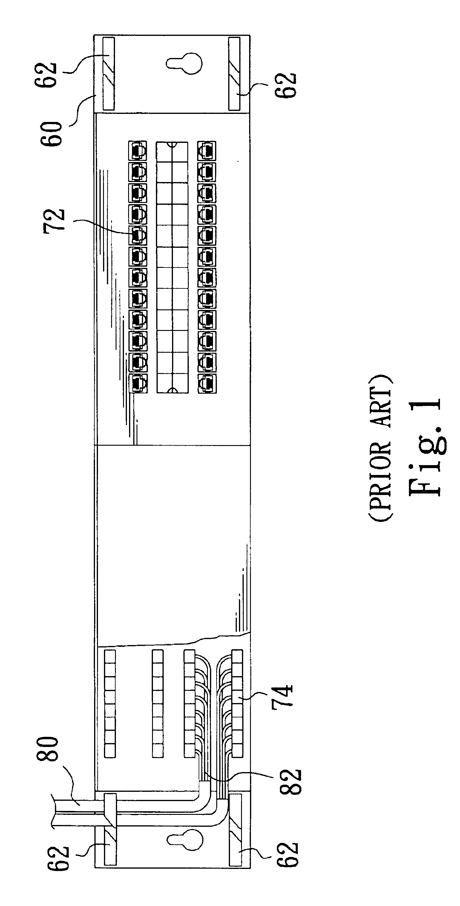
If network cables are come from the parallel direction of the patch panel, it will be inconvenient to arrange the network cables.
Therefore, the double twisted network wires designed to prevent EMI are separated into two parallel wires with different lengths which result high cross-talk and lower telecommunication quality.

Method used


Image

  • Advanced patch panel
  • Advanced patch panel
  • Advanced patch panel

Examples


first embodiment

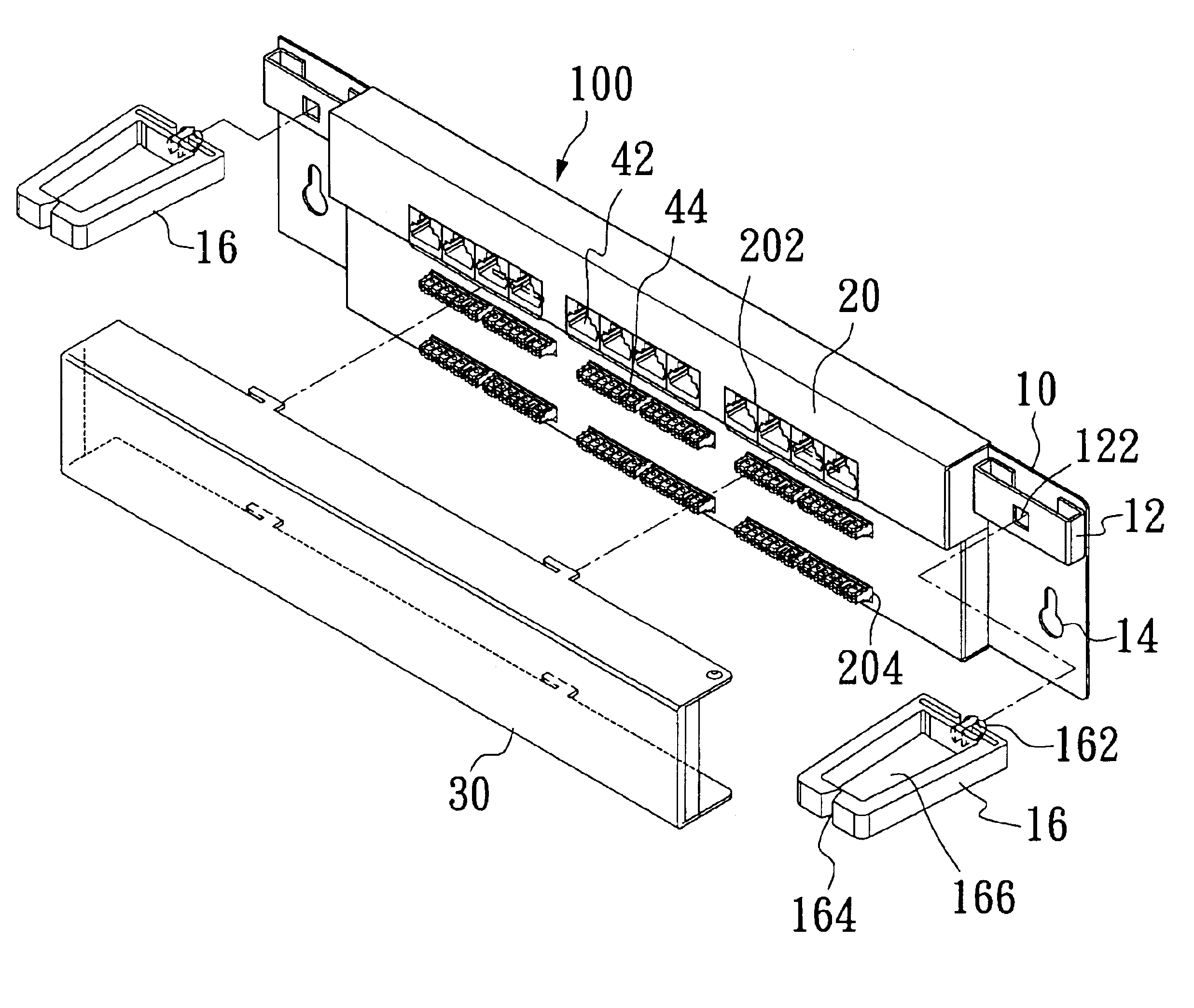
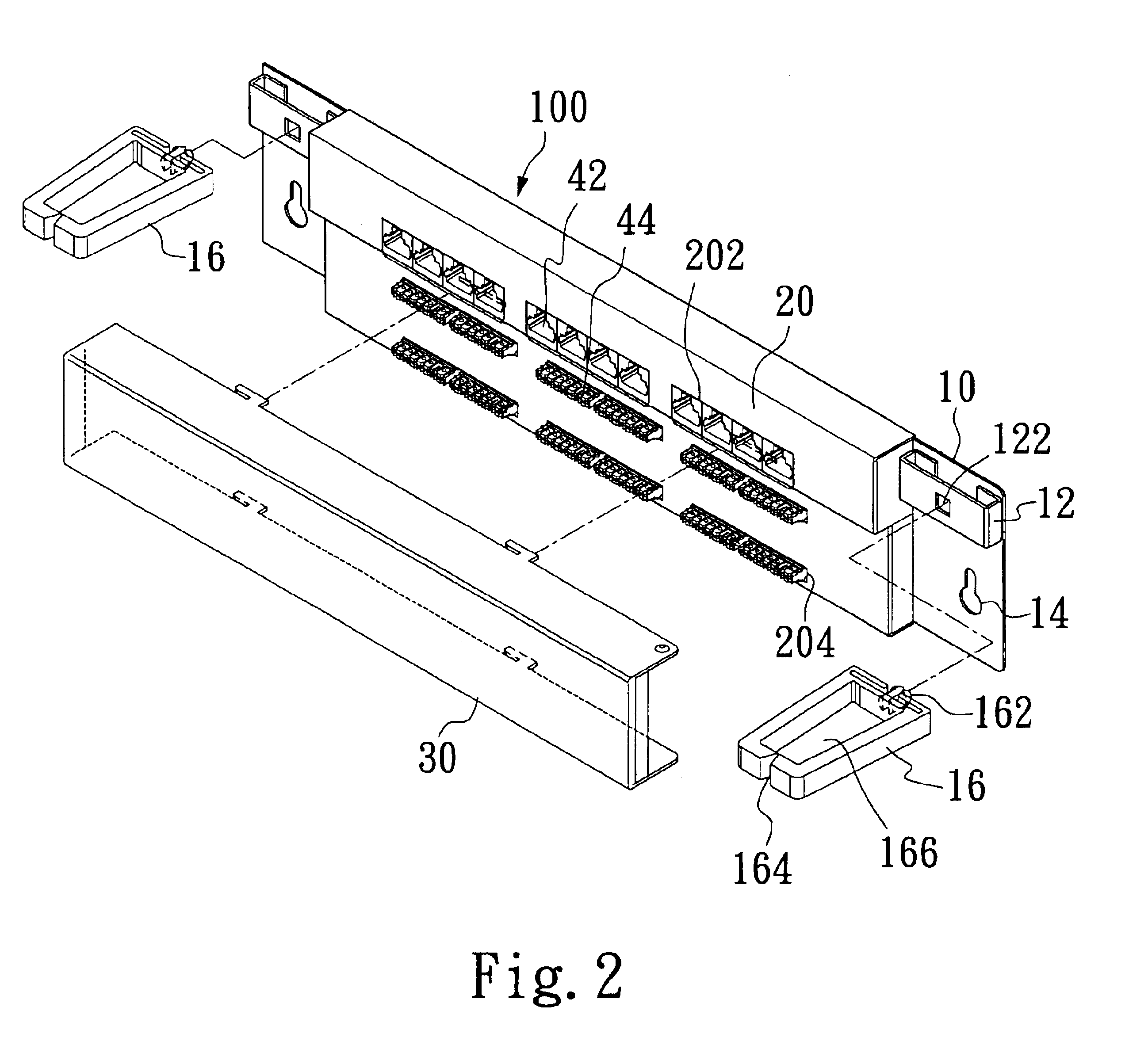
[0015]Referring to FIG. 4 illustrated the front view of the present invention, four sets of double twisted network wires (not shown) in each network cable 50 are separated into eight network wires 52, and each network wire 52 is embedded into IDC sets 44 respectively according to colors, and each IDC sets 44 is divided into one upper line and one lower line, and each line has four ports. The eight network wires 52 are plugged into the upper line and the lower line of IDC sets 44 respectively according to colors. Therefore, in one line, the length differences of the network wire plugged in the first left port and the one plugged in the first right port is not too large to result cross-talk.

second embodiment

[0016]Referring to FIG. 5 illustrated a front view of the present invention, which describes how the cable split ring 16 positioned vertically on the patch panel 100 arranges the network cables parallel to the patch panel 100. The network cable 50 are placed to the cable placer 166 from the side of the back board 10, and then the outer covering layer of the network cable 50 are cut. Then four sets of double twisted network wires 52 are embedded into the four ports of the upper line and those of the lower line of IDC sets 44 according to each network wire's color, and each jack 42 is responsed to a IDC set 44. Therefore, the network wires 52 in the external network cables 50 are plugged into the upper and the lower lines of IDC sets 44, and IDC sets 44 connect with jacks through electrical circuits on the electrical board, and then the external network cable 50 can connect with the internal network wires, such as RJ-45.

[0017]According to the present invention, each IDC set is divided...


PUM


Abstract

A patch panel mainly includes a panel with support holes which may be of rectangular shape and is located on each side of the panel; an electric circuit board mounted on the panel, which is structured a plurality of jacks and a plurality of IDC sets (Insulation Displaced Contact); the plurality of jacks separated into at least one set, which are parallelly located on the electric circuit board; the plurality of IDC sets separated into upper and lower sets, which are parallelly located on the electric circuit board and electrically connect with the plurality of jacks; a plurality of cable split rings with flexible holders to be plugged into the support holes oriented horizontally or vertically; and a cover with a plurality of openings, which covers the electric circuit board and exposes the jacks and the IDC sets.

Description

FIELD OF THE INVENTION[0001]The present invention relates to a patch panel, and more particularly to a patch panel having a wires-easy arranged and low-cross-talk patch panel thereon.BACKGROUND OF THE INVENTION[0002]Following a trend of net communities and net office buildings, a machine room's setup is not as simple as before. Extranet cables of the machine room, such as 256Kbytes, 512Kbytes, T1 or T3, can be provided by ISP (Internet Service Provider), and then be separated as intranet cables to each home of the communities and to each company of the office building, and then finally separated to each room of the home and each seat of the office. Due to the home moving in the communities and the seat changing in the office, original intranet cables could be moved to new homes and seats, and IP addresses needn't to be reconfing again. Therefore, how to smoothly arrange the original complex network cables and how to avoid cross-talk interference between network cables are the key po...

Claims


Application Information

Patent Timeline
Patent Type & Authority Patents(United States)
IPC IPC(8): H01R9/24H01R4/24
CPCH01R9/2416H01R4/24Y10S439/941
Inventor MA, TSU-YUAN
Owner HSING CHAU INDAL
Learn More