
Method and system for emulating a single router in a switch stack

a technology of switch stack and router, which is applied in the field of network computer systems, can solve the problems of limiting the scalability of configurations such as those shown in fig. 2 and 3

Inactive Publication Date: 2005-08-23
INTEL CORP
View PDF6 Cites 95 Cited by
  • Summary
  • Abstract
  • Description
  • Claims
  • Application Information

AI Technical Summary

Problems solved by technology

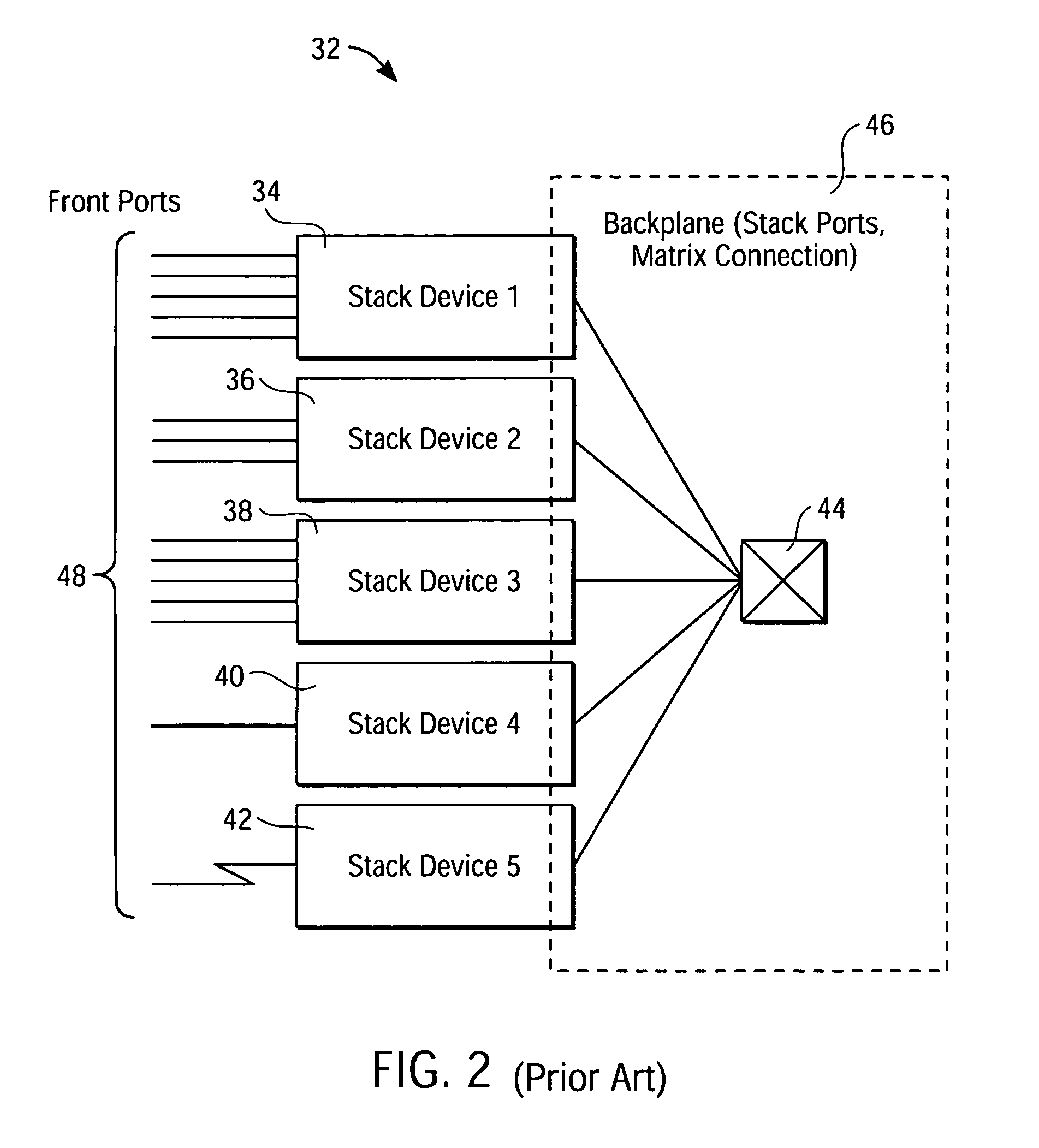
However, configurations such as those shown in FIGS. 2 and 3 suffer from several drawbacks.
Further, inter-switch connections of the switch stack 32 limit their scalability.

Method used


Image

  • Method and system for emulating a single router in a switch stack
  • Method and system for emulating a single router in a switch stack
  • Method and system for emulating a single router in a switch stack

Examples


case 1

[0034]Case 1: Layer 3 or Layer 4 Asymmetric Routing.

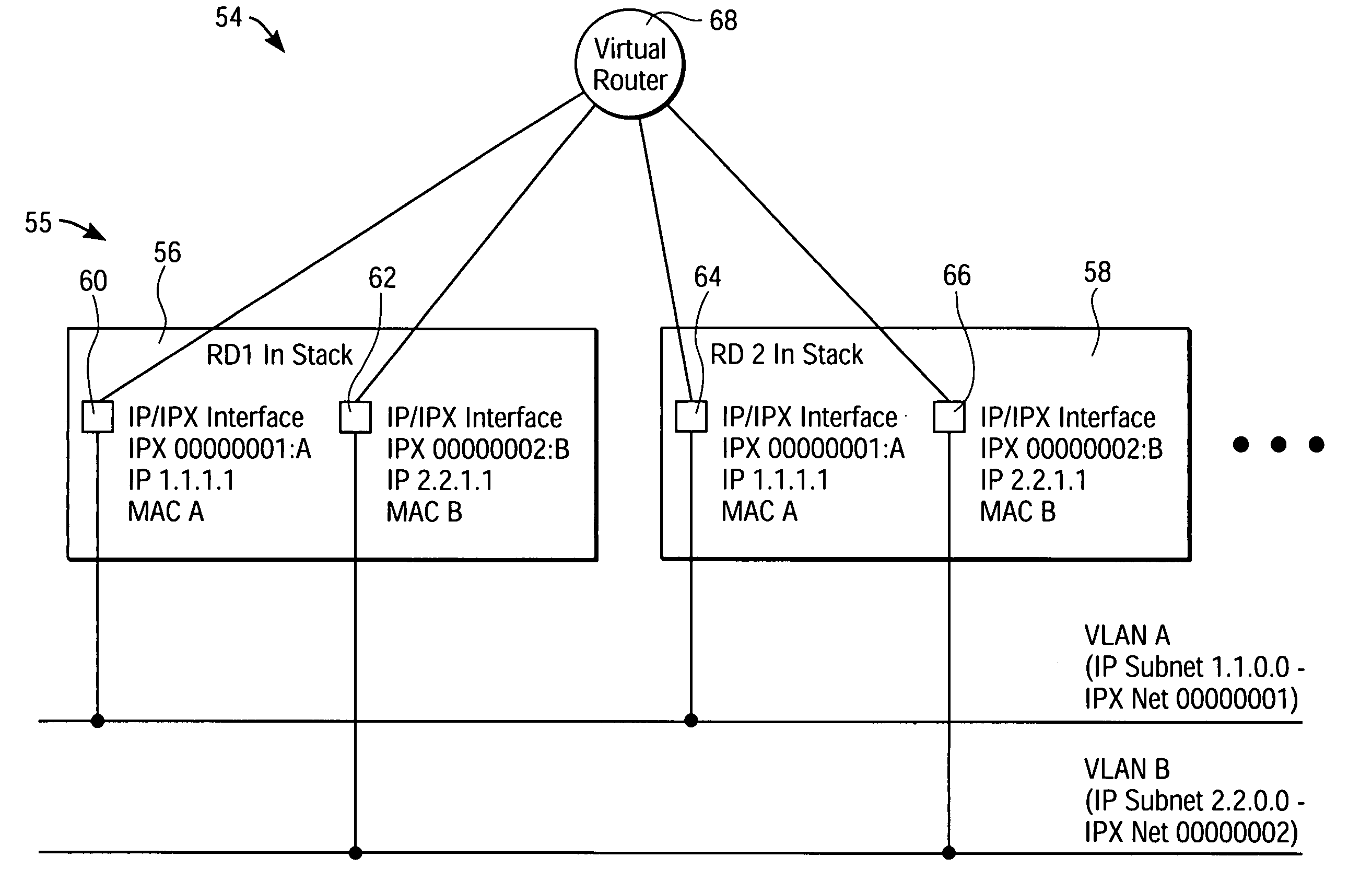
[0035]FIG. 7 illustrates an example of an asymmetric routing procedure for the switch stack 54 of FIGS. 4 and 5. In FIG. 7, a packet is to be routed from a sending node (such as the station 78 or “Node a”) in the VLAN A to a receiving node (such as the station 80 or “Node b”) in the VLAN B. Node a is connected to the RD 56 via a front port F1, with Node a having a MAC address of “MAC a.” Node b is connected to the RD 58 via a front port F2, with Node b having a MAC address of “MAC b.” The packet is sent from Node a in the VLAN A to the first IP / IPX interface 60 of the RD 56, with the packet being sent with a destination MAC (DMAC) address of “MAC A” for the IP / IPX interface 60, a source MAC (SMAC) address of “MAC a” for Node a, a destination IP (DIP) address for Node b, and a source IP (SIP) address for Node a. The RD 56 then routes the packet to the second IP / IPX interface 62 of the RD 56, and from there, the packet is sent on a s...

case 2

[0038]Case 2: NRD Filtering.

[0039]Because all RDs in the switch stack 54 share the same MAC address, such as the “MAC A” address for the IP / IPX interfaces 60 and 64 that corresponds to the VLAN A shown in FIG. 7, a unicast packet sent from a node in a VLAN and having a destination address of “MAC A” can potentially go to any of the RDs. Therefore, NRDs according to an embodiment of the invention include a filtering mechanism that enables the NRD to forward a unicast packet received from one of its VLAN nodes and destined for “MAC A” to a router MAC address of the specific RD that owns the NRD and to no other RD.

case 3

[0040]Case 3: Nodes Send a Multicast / Broadcast Packet Requiring a Unicast answer.

[0041]In this situation, only one RD needs to send a unicast reply to the node that sent the multicast / broadcast packet. The RD that sends the unicast reply can be chosen as the RD that receives, on an “owned” port as previously described above, the multicast / broadcast packet from the node.


PUM


Abstract

A system and method for emulating a single router in a switch stack is described. The switch stack is connected to virtual local area networks (VLANs) and comprises a number of stack devices that can include routing devices (RDs) having interfaces to the VLANs and non-routing devices (NRDs). All of the interfaces of the RDs share the same router and VLAN configuration addresses, including router Media Access Control addresses. One RD is appointed as a master in the switch stack and all other RDs use the configuration addresses of the master. Each NRD is owned by a corresponding routing device according to an ownership algorithm. The shared configuration addresses allow the switch stack to appear as a “virtual router” to nodes belonging to VLANs connected to the switch stack.

Description

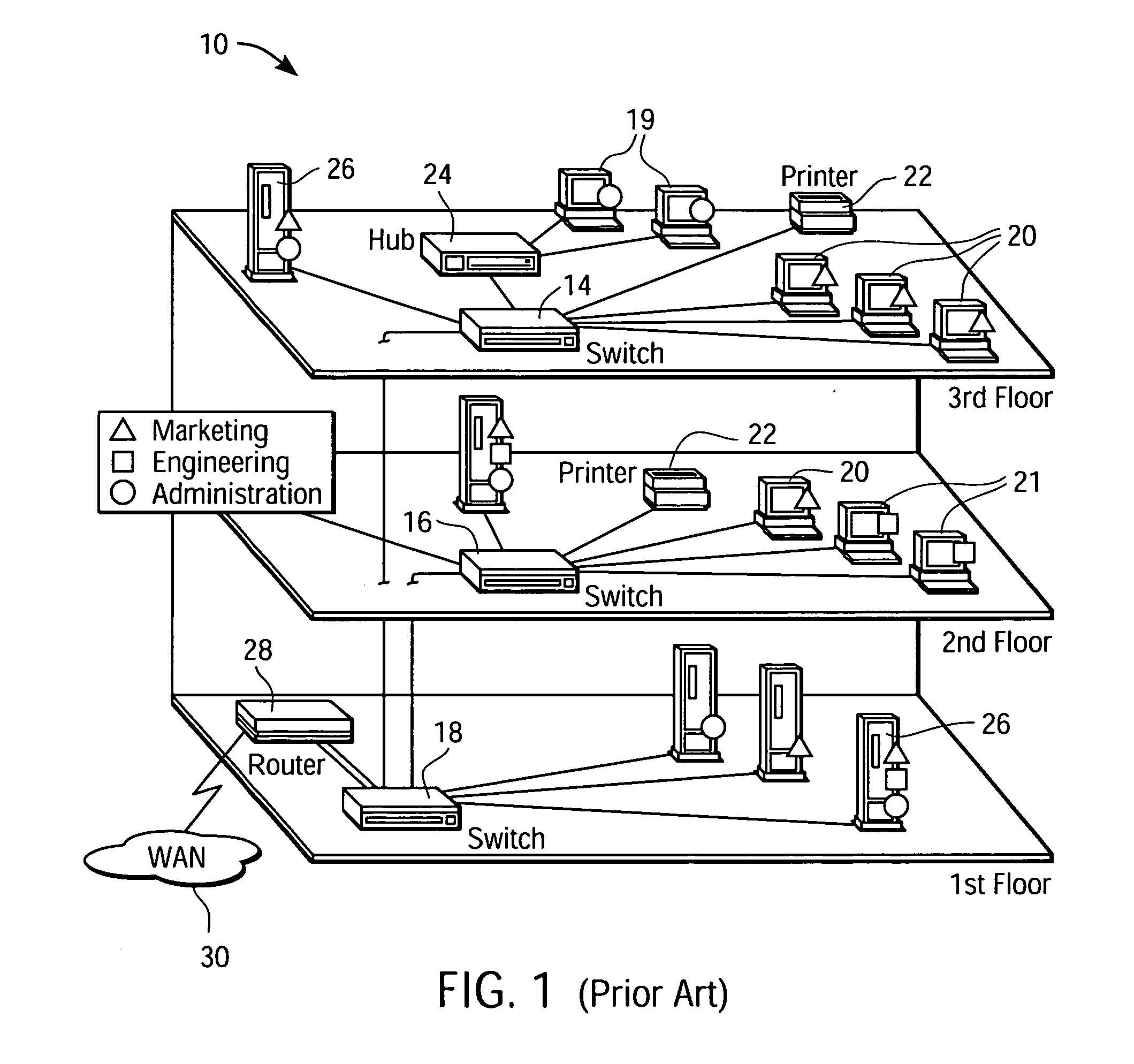
BACKGROUND OF THE INVENTION[0001]1. Field of the Invention[0002]The present invention relates generally to networking computer systems, and more particularly to networking computer systems having devices that emulate a single router in a switch stack.[0003]2. Background Information[0004]A virtual local area network (VLAN) is a group of personal computers (PCs), servers, and other network resources and stations that behave as if they were connected to a single network segment, as determined by some network administrator-defined criteria. For example, all marketing personnel may be spread throughout a building, but if they are all assigned to a single VLAN, they can share resources and bandwidth as if they were connected to the same segment.[0005]FIG. 1 illustrates an example of a building 10 having one or more VLANs. The VLANs are segmented from each other by one or more switches 14, 16, 18 operating at the Media Access Control (MAC) sublayer of the Data Link layer (Layer 2) of the I...

Claims


Application Information

Patent Timeline
Patent Type & Authority Patents(United States)
IPC IPC(8): H04L12/56
CPCH04L49/354H04L49/40
Inventor AMMITZBOELL, BENNY L.
Owner INTEL CORP
Learn More