
Permanent and semi-permanent groyne structures and method for shoreline and land mass reclamation

a groyne structure, permanent and semi-permanent technology, applied in the direction of groynes, piers, agriculture tools and machines, etc., can solve the problems of only practicality, personal and economic loss, and adversely affect the general public,

Inactive Publication Date: 2005-08-23
BENEDICT ENG
View PDF28 Cites 13 Cited by
  • Summary
  • Abstract
  • Description
  • Claims
  • Application Information

AI Technical Summary

Benefits of technology

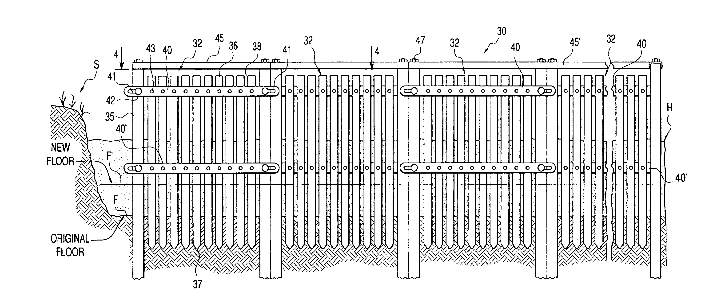
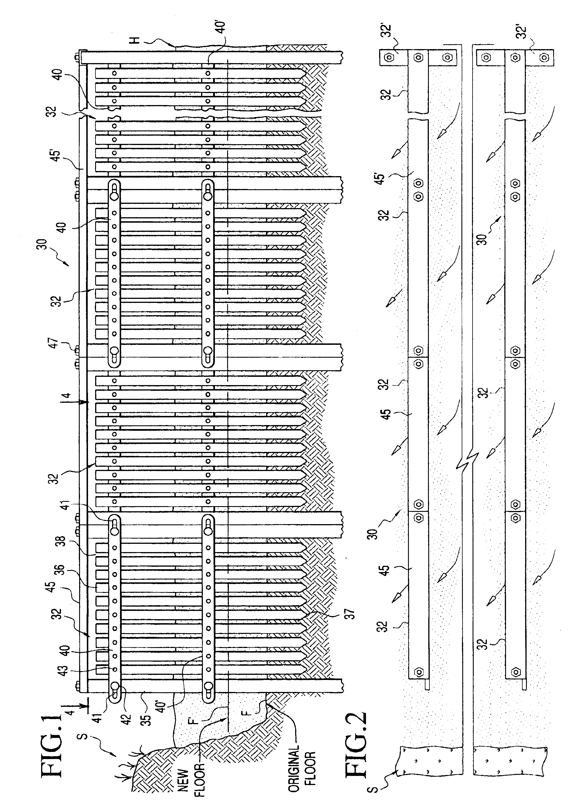
[0018]In the preferred embodiments, each groyne section, which includes a pair of spaced stanchions and an intermediate set of baffle elements, are designed to be driven into the sea floor as an unit such as by jetting, vibrating, drilling, impact driving and the like. To facilitate the placement of each unit of the groyne structures, an upper cap member may be provided which extends between the upper end of each stanchion and is secured thereto, thereby rigidity each unit when the unit is placed into service.
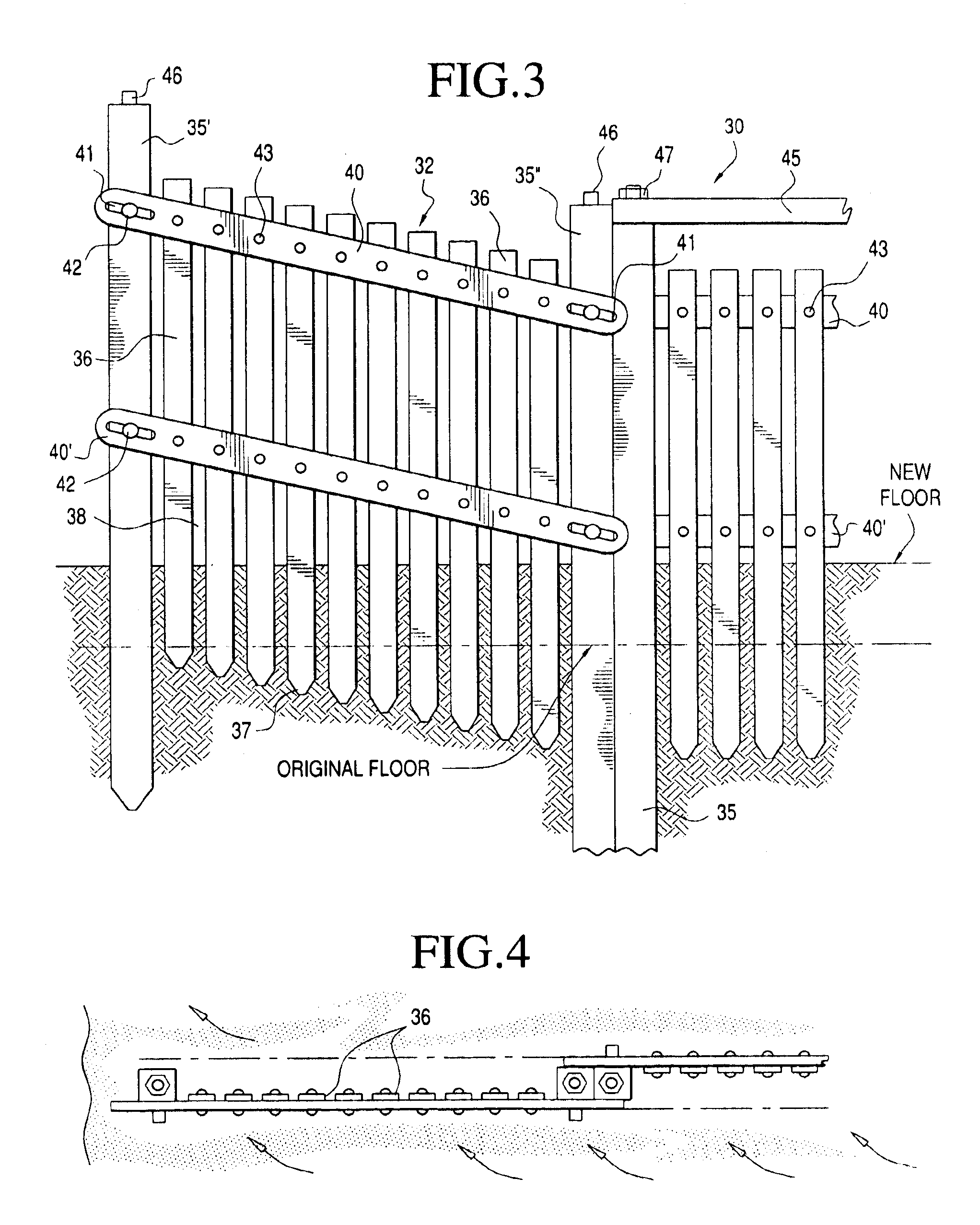
[0020]The groyne structures of the invention are specifically designed so that they may be permanently placed into service for a prolonged period of time, such as for years. However, one of the benefits of the structures of the invention is that they may also be treated as semi-permanent structures. Therefore, when environmental or other conditions require, the structures may also be readily vertically adjusted or removed. In this respect, because of the relationship between the stanchions and the reinforcing bars and the baffle elements, it is possible to elevate the stanchion sections by raising one of the stanchions of each section at a time. The reinforcing bars act as a pivot linkages between the stanchions and, when two or more bars are used and placed in parallel relationship with respect to one another, they act as parallel linkages. Because of the relative movement which is possible between the reinforcing bars and each stanchion due to the elongated slots in the bars, one stanchion may be elevated relative to the other stanchion of a section while maintaining the integrity of the spacing of the baffle elements relative to one another such that they remain in parallel vertical relationship with respect to one another when being raised. In order to raise each groyne section, any upper cap member associated therewith may be removed prior to the elevation of the section.
[0026]In those embodiments where the baffle elements are suspended by integrally formed tongues or interfitted with respect to one another, it is not necessary for the elements to be pivoted or otherwise attached to the horizontal reinforcing linkage bars. This facilitates the manner in which the groyne structures can be assembled and reduces the overall cost by reducing the number of pivot points which are necessary with each groyne structure. By suspending each of the vertical members from a common hanger and by providing the pivot linkage between the stanchions and reinforcing bars, it is still possible to raise one end of a groyne section relative to the other end even with a plurality of stanchions provided in each section.
[0028]It is a primary object of the invention to provide a method and apparatus for economically reclaiming land including along shorelines and off shore areas of oceans, gulfs, inlets, bays, rivers, lakes as well as other areas wherein currents, wave, tidal or other activities are experienced and wherein the structures exhibit permanent or semi-permanent characteristics being sufficiently strong and rigid to withstand the stresses imparted by strong storm surges and heavy tidal activity.

Problems solved by technology

Not only is there a tremendous personal and economic loss caused by damage to, or loss of, real estate, housing and commercial buildings by shoreline or beach erosion, but there is also recreational loss of waterfront property which adversely affects the general public.
Such structures are costly and are only practical when population densities make it economically reasonable to construct them.
Further, such structures have an adverse effect on the natural appearance of the shoreline and, in many areas, cannot be practically constructed.
Like seawalls, however, such structures are costly to construct and maintain and, in some areas, are not appropriate for use due to the shoreline configuration, prevailing currents or tidal activity and the like.
Also, such structures create a safety hazard in areas where recreational activity is anticipated.
Again, such outer barriers are only appropriately used in some locations and are not appropriate for use in many locations and may be objectionable for use in some areas due to the adverse affect on aquatic life.
Such methods of shoreline reclamation, however, are temporary measures, at best, and do not provide a long-term solution to shoreline erosion.
Further, such restoration methods are extremely costly and are not practical in many locations.
The removal of the netting material can adversely affect the restored shoreline by creating trenches or furrows which form natural channels in which water flows away from the shoreline thereby conveying particulate matter back to a body of water.
During use, flexible materials such as screening and netting are effective for material build-up, however, under some deployment conditions such as during violent storms and sea surges, such groyne structures can be significantly damaged.
Damage to screening or netting mandates added cost for required repair and replacement in order to maintain an effective groyne system.

Method used


Image

  • Permanent and semi-permanent groyne structures and method for shoreline and land mass reclamation
  • Permanent and semi-permanent groyne structures and method for shoreline and land mass reclamation
  • Permanent and semi-permanent groyne structures and method for shoreline and land mass reclamation

Examples


first embodiment

[0060]With continued reference to drawing figures, groyne 30 is shown as being deployed along shoreline “S” of a gulf, ocean, lake, river or the like such that the structure extends along the shoreline to off shore with the height of the structure being such that it extends generally above a high water line “H”. The groyne structure is designed to be permanent or semi-permanent however, when environmental or other conditions require, the groyne may also be readily elevated or removed or adjusted so as to not adversely affect movement of aquatic life.

[0061]The groyne 30 includes a plurality of groyne sections or units 32 which are positioned generally in alignment with one another extending from the shoreline to offshore. The alignment with respect to the shore may be substantially perpendicular, as shown in FIG. 2 wherein two groyne structures are shown as being in generally parallel relationship with respect to one another. As opposed to extending perpendicularly from the shoreline...

second embodiment

[0078]With specific reference to FIGS. 5 through 9, the invention is disclosed in greater detail. In this embodiment, groyne 50 is shown as including a plurality of groyne sections 52 which are interconnected with one another to form an extended groyne extending outwardly from the shoreline. As with the previous embodiment, shorter groyne sections 52′ may be provided generally perpendicularly thereto at the outer end of the groyne structure to provide a breakwater. In this embodiment, a plurality of stanchions 55 are provided in spaced relationship with respect to one another along the length of the groyne as shown in FIG. 3. Although the groyne sections 52 may be formed in the same general manner as the embodiment of FIG. 1 wherein each section includes opposite end stanchions, the separate sections may be somewhat integrally formed such that there are no intermediate pairs of stanchions along the length of the groyne. Intermediate each of the stanchions 55 are a plurality or set o...


PUM


Abstract

The method and apparatus for shoreline land mass reclamation which includes replacement of at least one groyne section along a shoreline wherein the section includes a pair of spaced stanchions which are connected by at least one linkage member which supports vertically extending baffle elements and wherein the at least one linkage member is piovtably connected such that the spaced stanchions may be vertically adjustable relative to one another.

Description

CROSS REFERENCE TO RELATED APPLICATION[0001]This application is a continuation of application Ser. No. 10 / 158,124, filed May 31, 2002 now abandoned, in the name of the same inventor. Benefit of the filing date of the parent application is claimed with respect to this application.BACKGROUND OF THE INVENTION[0002]1. Field of the Invention[0003]The present invention is directed to porous groyne-like structures and method for their use in reclaiming beaches, shoreline areas and other land masses which are subject to erosion by natural forces and, more specifically, to permanent and semi-permanent groyne structures which may be left in place when deployed. In some embodiments the groynes may be systematically raised as reclamation progresses from the buildup of silt, sand, shells, dirt, twigs and branches, grasses and other materials.[0004]2. Description of Related Art[0005]Beach and other shoreline erosion, especially in coastal areas, is a major concern to property owners who have resi...

Claims


Application Information

Patent Timeline
IPC IPC(8): E02B3/04
CPCE02B3/04
Inventor BENEDICT, CHARLES E.
Owner BENEDICT ENG
Learn More