Radiator cap with pressure valve
- Summary
- Abstract
- Description
- Claims
- Application Information
AI Technical Summary
Benefits of technology
Problems solved by technology
Method used
Image

Examples
first embodiment
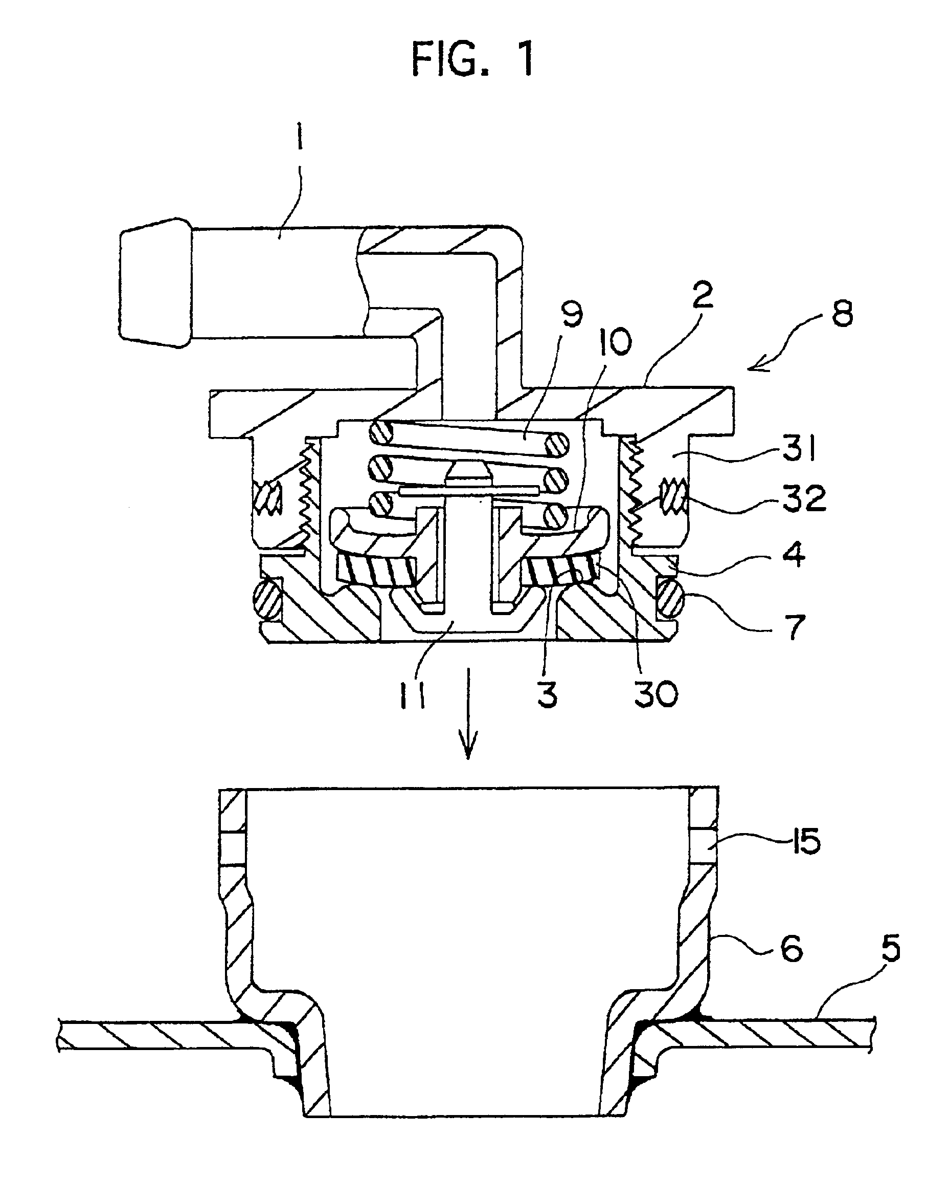
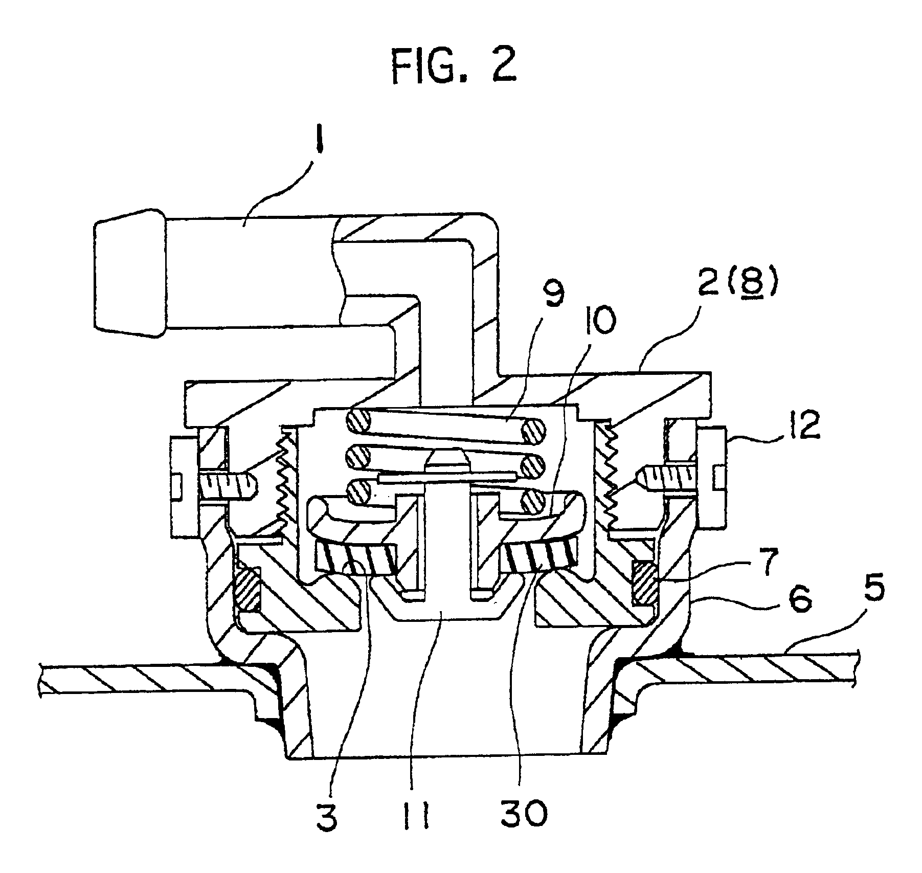
[0034]FIG. 1 is a longitudinal sectional view of a cap body 8 and a filler neck 6, showing the present invention. FIG. 2 shows the state of mounting thereof.
[0035]The cap body 8 comprises an upper member 2 and a lower member 4 which are each made of a synthetic resin injection-molded part, a pressurization valve 10 and a negative pressure valve 11. The upper member 2 is in the form of an upper lid which includes a small-diameter pipe 1 for cooling water guidance extending integrally centrally from the upper end, and a short tubular potion 31 extending from the underside of the upper member 2, with a pair of threaded blind holes 32 formed in the outer periphery of the tubular portion 31.
[0036]The lower member 4 is formed as a cylinder separate from the upper member 2 and includes a valve seat 3 in the shape of an inner flange extending along its lower end inner periphery, with its upper end outer periphery being secured to the inner periphery of the upper member 2 by screwing or othe...
second embodiment
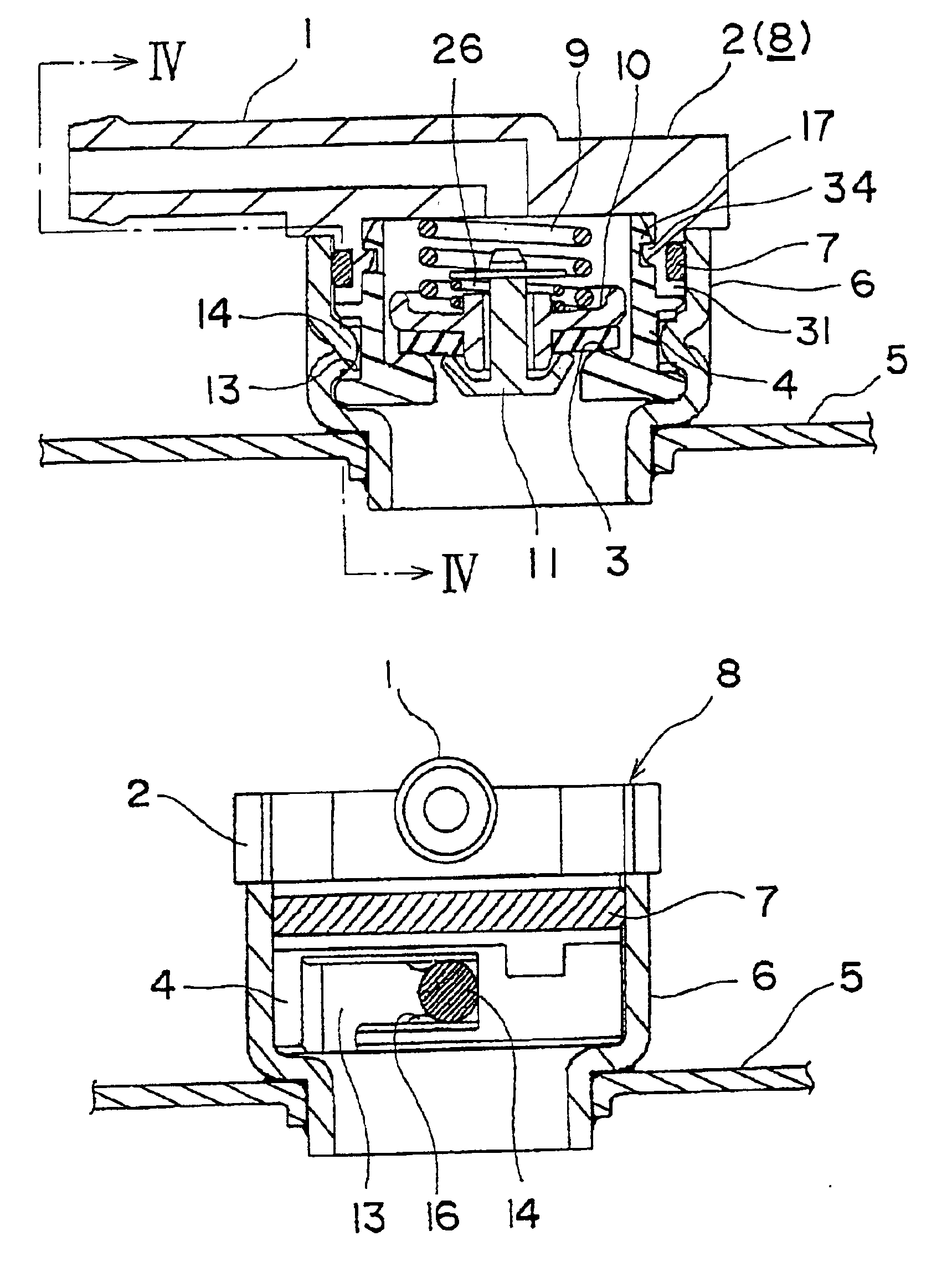
[0041]FIG. 3 is a longitudinal sectional view showing the present invention and FIG. 4 is a sectional view taken along a line IV—IV of FIG. 3. FIG. 5 is a top plan view of the filler neck 6; FIG. 6 is a front elevational view of the same; FIG. 7 is a front elevational view of the lower member 4 which is a constituent element of the cap body 8; FIG. 8 is a top plan view of the same; FIG. 9 is a longitudinal sectional view of the same; FIG. 10 is a longitudinal sectional view showing the state of assembly of the cap body 8; FIG. 11 is a top plan view of the same; and FIG. 12 is a front elevational view of the same.
[0042]This embodiment differs from the first embodiment in that the upper member 2 has on its outer peripheral side the groove for receiving the sealing material 7 and that the lower member 4 has at its upper end a multiplicity of locking claws 17, with engaging portions 34 in registration therewith formed in the inner surface of the tubular portion 31 of the upper member 2....
PUM
 Abstract
Description
Claims
Application Information
 - R&D
- Intellectual Property
- Life Sciences
- Materials
- Tech Scout
- Unparalleled Data Quality
- Higher Quality Content
- 60% Fewer Hallucinations
Browse by: Latest US Patents, China's latest patents, Technical Efficacy Thesaurus, Application Domain, Technology Topic, Popular Technical Reports.
© 2025 PatSnap. All rights reserved.Legal|Privacy policy|Modern Slavery Act Transparency Statement|Sitemap|About US| Contact US: help@patsnap.com