
Current loop control circuit for a time of flight ranging system

Inactive Publication Date: 2005-08-16
SIEMENS AG
View PDF3 Cites 4 Cited by
  • Summary
  • Abstract
  • Description
  • Claims
  • Application Information

AI Technical Summary

Benefits of technology

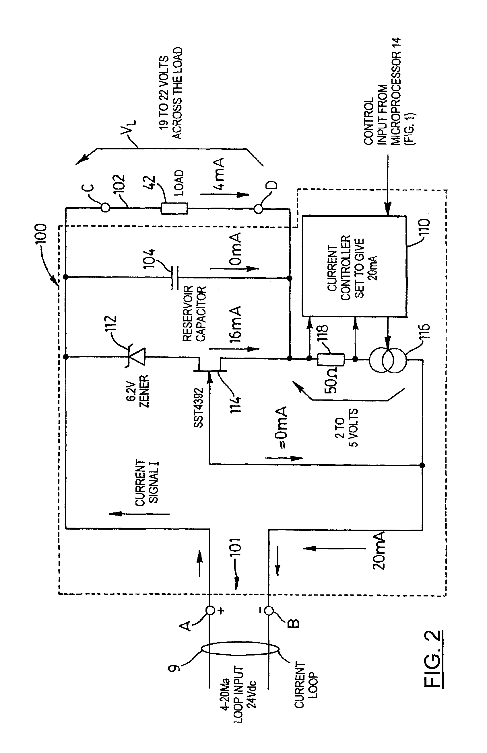
[0007]The present invention provides a current controller suitable for use with a process variable measurement transmitter operating with a remote receiver on a current loop. The current controller comprises a circuit that efficiently utilizes the current in the loop to produce an optimal voltage and current for the process variable measurement transmitter.

Problems solved by technology

A limitation of such loop powered transmitters has been that they must be able to operate at the minimum level of loop current, typically 4 mA.
A power deficit results in halting the program execution, and hence of measurement processes controlled by the microprocessor, until the deficit is made up, such that the program executes intermittently, the extent of the intermittence depending on the extent to which the normal operating power requirement exceeds the available power.
However, in situations where the current loop provides more power then is required by the circuitry, the excess power is dissipated as heat.

Method used


Image

  • Current loop control circuit for a time of flight ranging system
  • Current loop control circuit for a time of flight ranging system
  • Current loop control circuit for a time of flight ranging system

Examples


Embodiment Construction

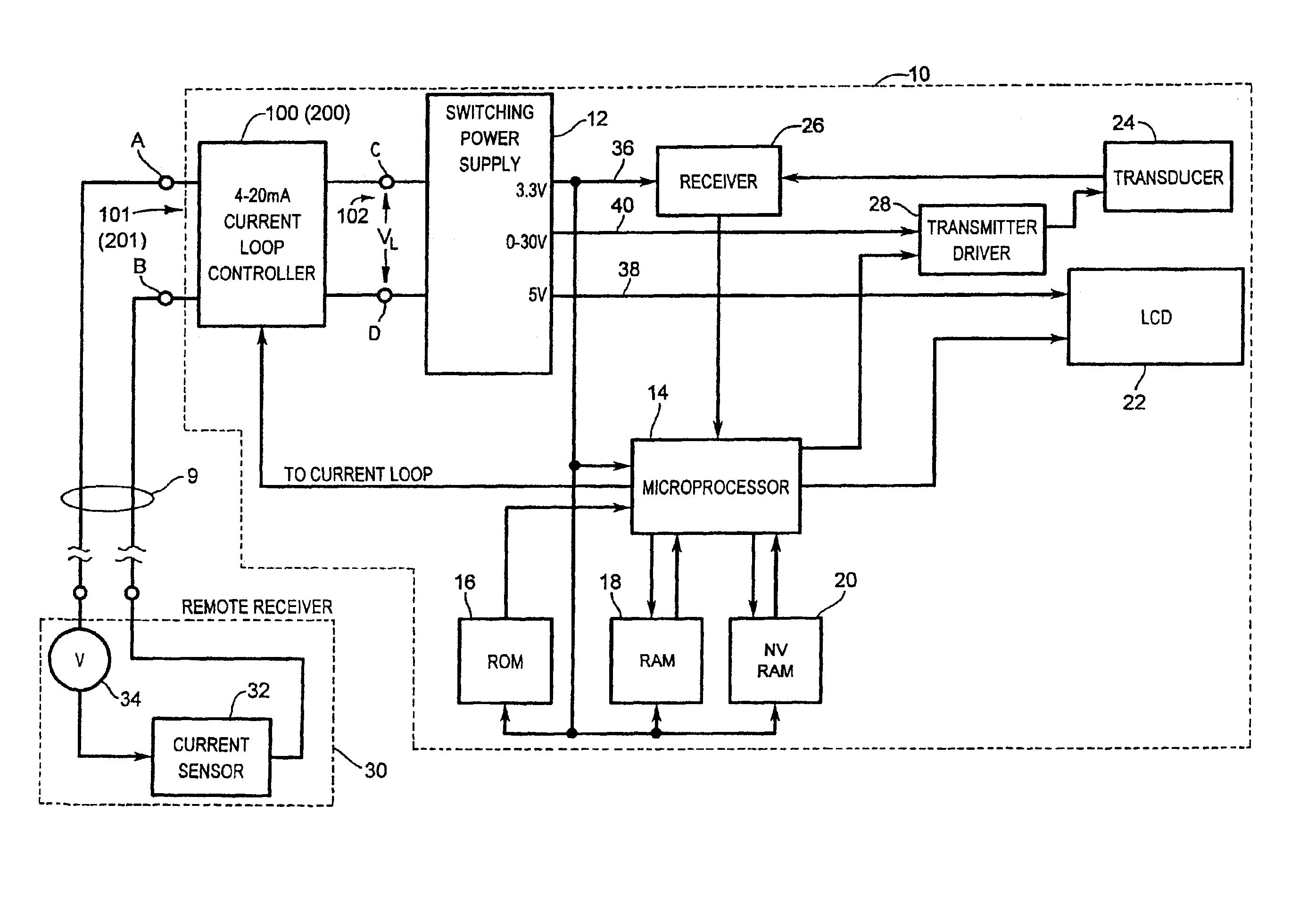
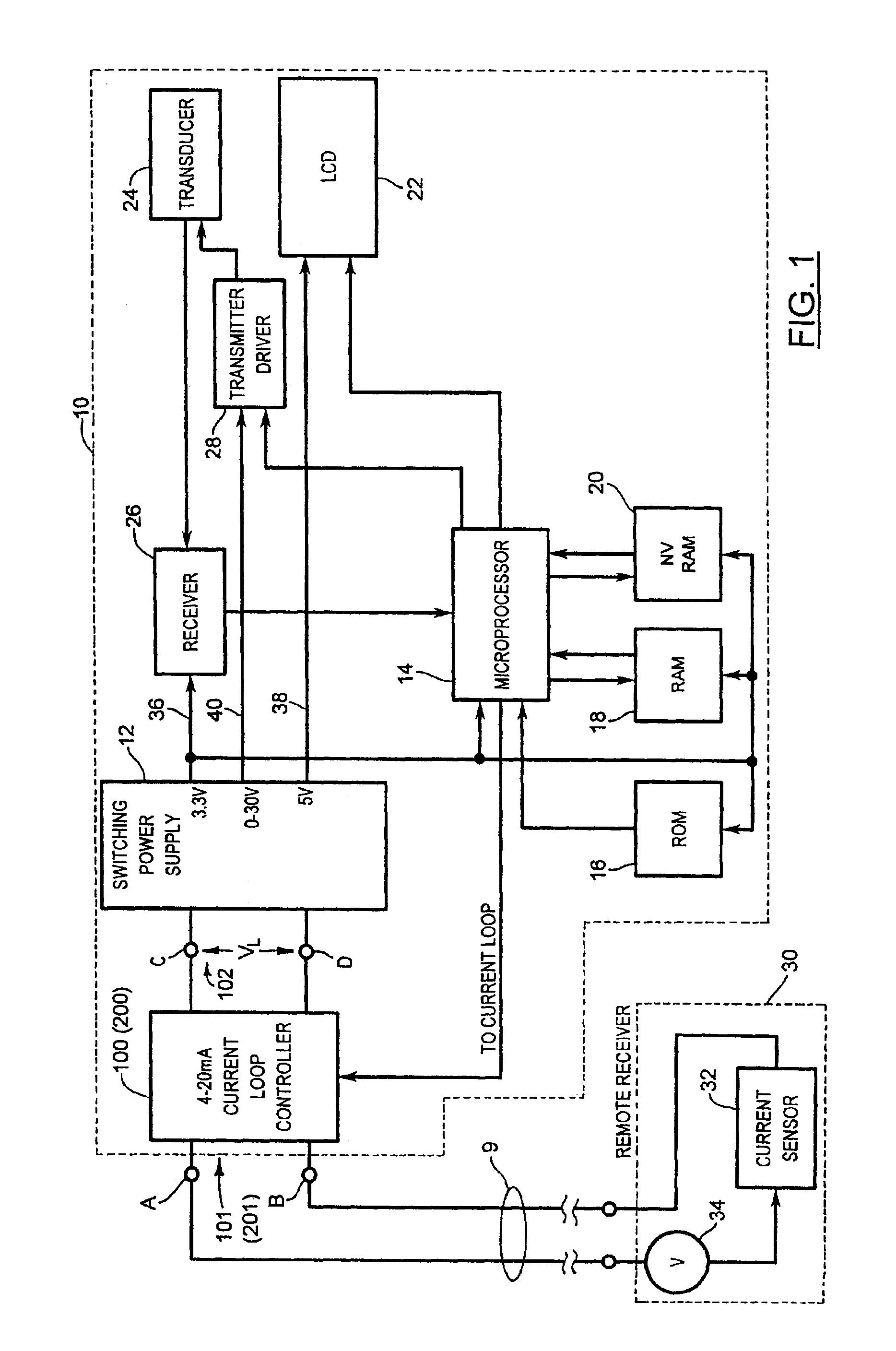
[0018]Reference is first made to FIG. 1, which shows in diagrammatic form a pulse echo ranging device 10 incorporating a 4-20 mA current loop control circuit or controller 100 according to the present invention. While the present invention is described in the context of time of flight ranging systems, and more specifically an ultrasound pulse echo system, it will be appreciated that the present invention has wider applicability to other types of time of flight ranging systems, such as radar or microwave based systems, and other types of process variable measurement devices, operating on a current loop.

[0019]The pulse echo ranging device 10 comprises a power supply 12, and a microprocessor 14. The microprocessor 12 is associated with a read only memory (ROM) 16 for storing a control program for the microprocessor 14, a random access memory (RAM) 18 providing scratch pad memory and temporary storage of variables, and a non-volatile memory 20 for storing operating parameters under powe...


PUM


Abstract

A current loop control circuit for a process variable transmitter coupled to a receiver at a remote location through a two-conductor current loop. The current loop control circuit efficiently utilizes the current in the loop to produce an optimal voltage and current for the operation of the process variable measurement transmitter.

Description

FIELD OF THE INVENTION[0001]The present invention relates to time of flight ranging systems, and more particularly to a two-conductor current loop control circuit for powering a time of flight ranging system.BACKGROUND OF THE INVENTION[0002]Time of flight ranging systems, are commonly used in level measurement applications, and referred to as level measurement systems. Level measurement systems determine the distance to a reflector (i.e. reflective surface) by measuring how long after transmission of a burst of energy pulses, an echo is received. Such systems typically utilize ultrasonic pulses, pulse radar signals, or microwave energy signals.[0003]Time of flight ranging systems are commonly utilized in remote locations where process variable data is transmitted to a central location for further processing or collection. A common means for transmitting such data is by a current loop. The value of the process variable is represented by the magnitude of a current passing through the ...

Claims


Application Information

Patent Timeline
IPC IPC(8): G01F23/284
CPCG01F23/284
Inventor MERCIER, CLAUDE
Owner SIEMENS AG
Learn More