
Vibration-proof glove and production method thereof

a technology of vibration-proof gloves and production methods, which is applied in the field of vibration-proof gloves, can solve the problems of high production cost, unusability, and difficulty in precisely forming the hollow at a specific portion of the glove, and achieve the effects of improving the usability of the glove, improving the flexibility of the glove, and facilitating production

Inactive Publication Date: 2005-08-16
ATOM
View PDF19 Cites 69 Cited by
  • Summary
  • Abstract
  • Description
  • Claims
  • Application Information

AI Technical Summary

Benefits of technology

"The present invention provides a vibration-proof glove that is designed for use in operations with vibration tools such as rock drills or engine cutters. The glove has a stretchy glove body made of knit and a vulcanized foam rubber material that is applied at least to the palm portion of the glove body. The foam rubber material is made of chloropylene rubber or natural rubber and a foaming agent added to the rubber material. The glove also has crosswise and lengthwise grooves on the palm portion of the glove body, which improve the flexibility and usability of the glove. The production method of the glove involves a rubber sheet with the rubber material and a foaming agent, followed by vulcanization and foaming of the rubber sheet after attaching it to the glove body. The vulcanized and foamed rubber material is flexible and easy to move a hand wearing the glove. The crosswise and lengthwise grooves on the foam rubber material further improve the flexibility and usability of the glove."

Problems solved by technology

However, there are drawbacks in the prior arts that those of the conventional gloves are complex in structure, high in production cost and uneasy to use.
For example, according to the glove provided with a hollow, it is difficult to precisely form the hollow at a specific portion of the glove.
Further, the hollow is broken by high vibrations and thus the usability of the glove is likely to decrease.
Further, those prior gloves are required to fasten an extra member such as a tube, pump for filling air or a vibration-insulation material, so that they are more complex in structure.

Method used


Image

  • Vibration-proof glove and production method thereof
  • Vibration-proof glove and production method thereof
  • Vibration-proof glove and production method thereof

Examples


Embodiment Construction

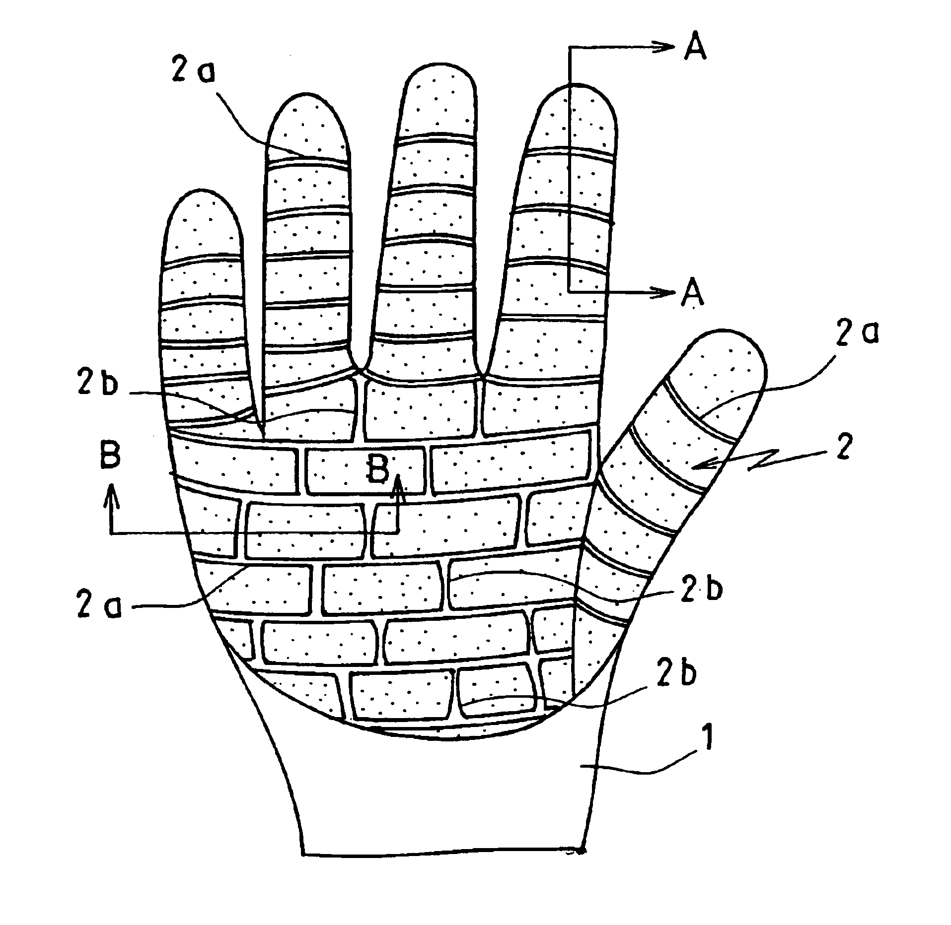
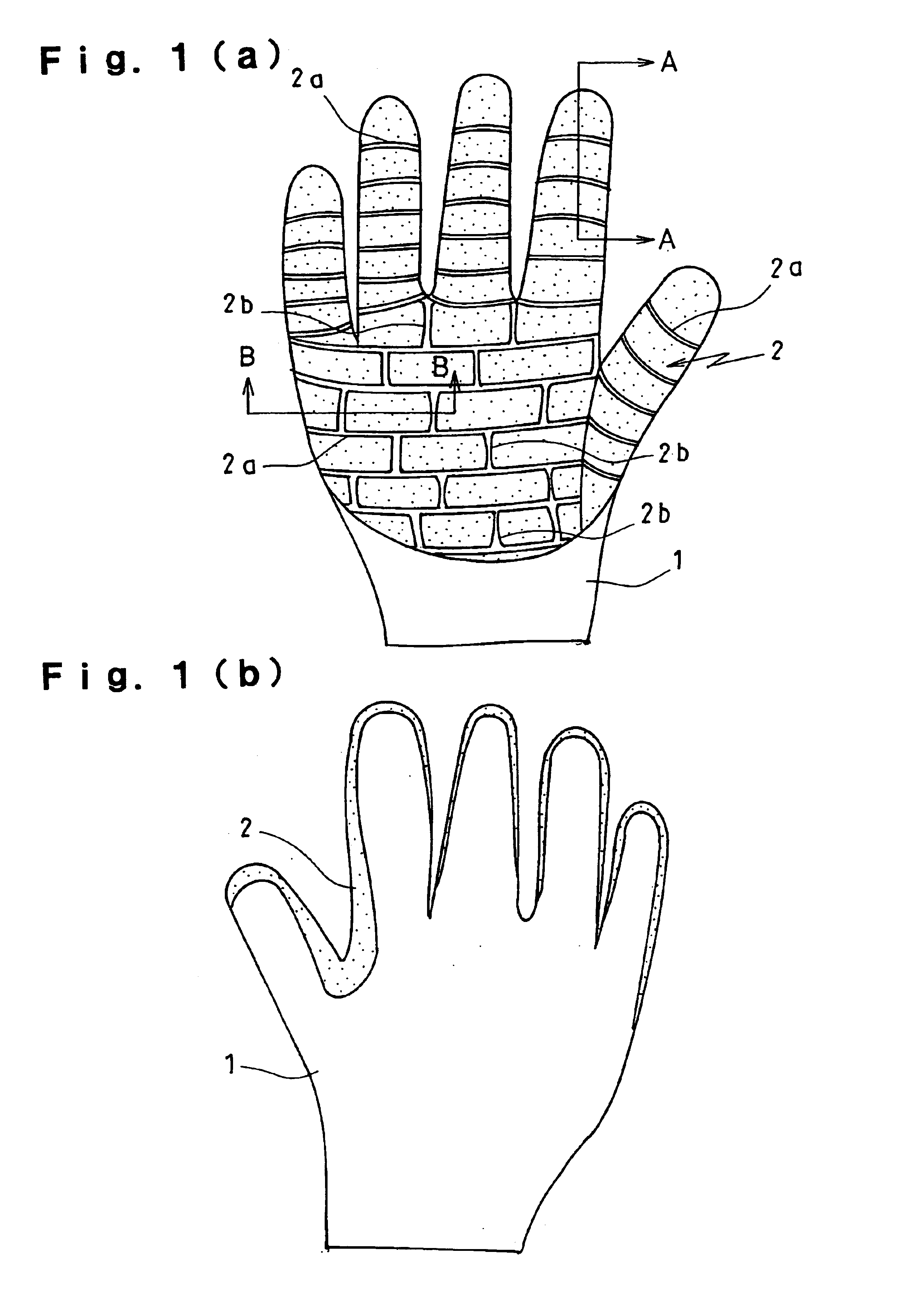
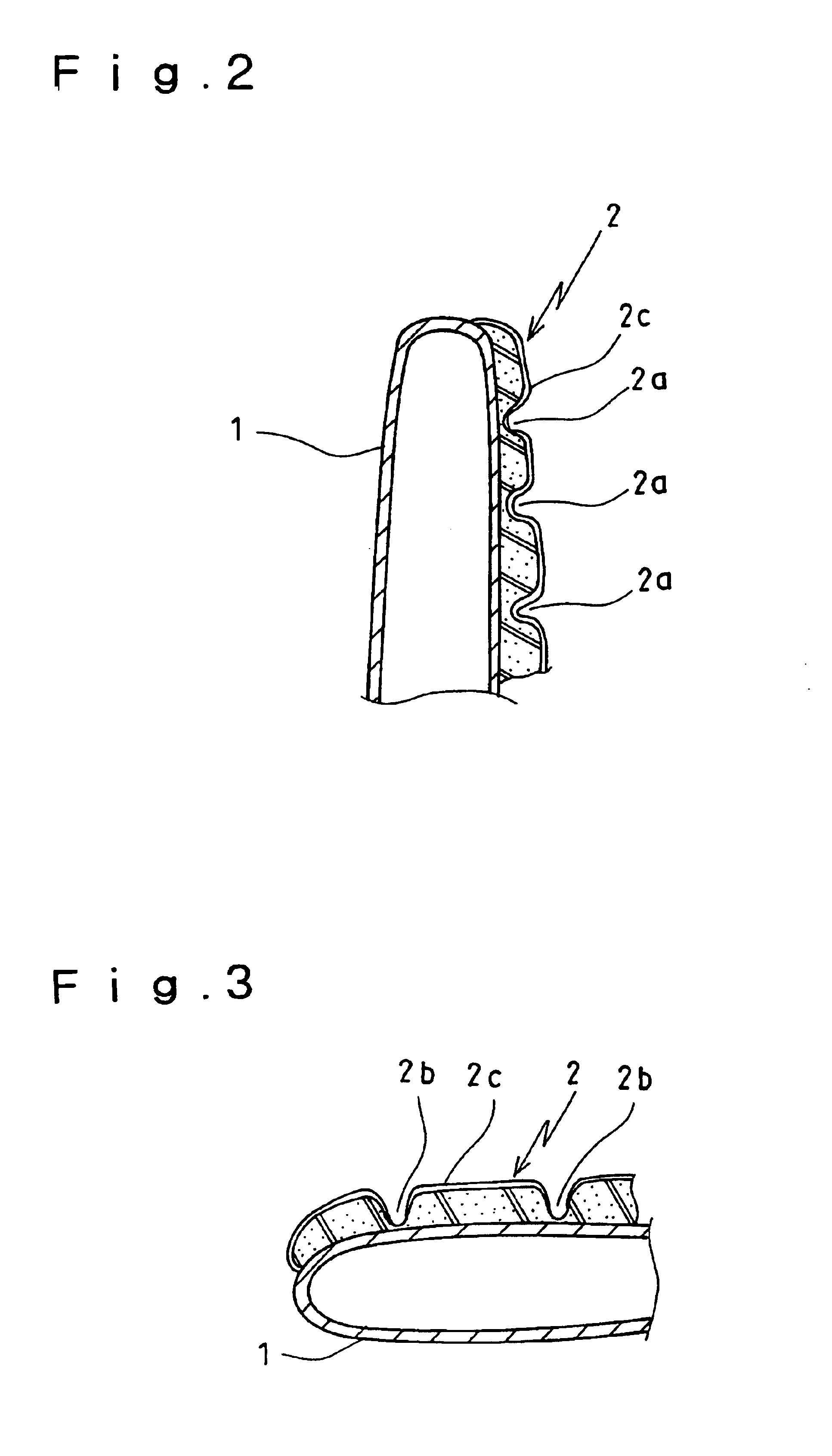
[0031]A vibration-proof glove according to the invention is described hereinafter referring to FIGS. 1 to 3. FIG. 1 illustrates a vibration-proof glove wherein the numeral (a) shows an elevation view of the palm portion of the glove while the numeral (b) showing an elevation view of a back portion of the glove. FIG. 2 illustrates an enlarged section view along line A—A in FIG. 1 (a). FIG. 3 illustrates an enlarged section view along line B—B in FIG. 1 (a).

[0032]A vibration-proof glove according to a preferred embodiment of the invention is wore in an operation with a vibration tool including a rock drill, engine cutter and the like. The glove comprises a knit made glove body 1 with high stretch property and a vulcanized foam rubber material 2 made of chloropylene rubber which is provided on the palm portion of the glove body 1 (the rubber material 2 can be made of natural rubber instead of chloropylene).

[0033]There are formed a plurality of crosswise grooves 2a throughout the palm p...


PUM

PropertyMeasurementUnit
temperatureaaaaaaaaaa
thicknessaaaaaaaaaa

Abstract

There is provided a vibration-proof glove which is wore particularly in an operation with a vibration tool such as a rock drill or engine cutter. The vibration-proof glove comprises a stretchy glove body 1 made of such as a knit material, and a vulcanized foam rubber 2 provided at least on the palm portion of the globe body. A plurality of crosswise grooves 2a or lengthwise grooves 2b are provided on the palm portion of the glove. The vulcanized foam rubber material 2 may be formed with chloropylene rubber or natural rubber.

Description

BACKGROUND OF THE INVENTION[0001]1. Field of the Invention[0002]This invention relates to a vibration-proof glove which is excellently effective in vibration absorption, simple in structure, low in production cost and easy to use.[0003]2. Description of the Prior Art[0004]Conventionally, vibration-proof gloves have been used in order to protect bodies of users from high vibrations during operations with so called vibration tools e.g., a rock drill or engine cutter.[0005]There are many types in vibration-proof gloves. For example, there is a type that a hollow or tube is provided in the palm portion of a glove, a type that air is filled in a glove when used, and a type that a insulation material is provided to a glove. See, for example, Japanese Unexamined Patent Publication No. 10-053908, Japanese Unexamined Patent Publication No. 2001-336007 and Japanese Unexamined Patent Publication No. 2002-013014.[0006]By wearing the above-mentioned vibration-proof gloves, high vibrations are re...

Claims


Application Information

Patent Timeline
Patent Type & Authority Patents(United States)
IPC IPC(8): A41D19/04A41D19/015A41D31/00A41D19/00B29D99/00
CPCA41D13/0587A41D19/01523A41D19/04A41D31/0044A41D31/28
Inventor TAIRA, SOUICHIROUKASHIHARA, TATSUO
Owner ATOM
Learn More