
Electric motor control unit

a technology of electric motors and control units, applied in the direction of dynamo-electric converter control, heating types, instruments, etc., can solve the problems of decreasing the life of circuit parts, undetectable high water temperature of radiators, damage of coils, etc., and achieve the effect of preventing damage to electronic circuit parts

Inactive Publication Date: 2005-08-09
YAZAKI CORP +1
View PDF14 Cites 21 Cited by
  • Summary
  • Abstract
  • Description
  • Claims
  • Application Information

AI Technical Summary

Benefits of technology

[0011]In view of the above-mentioned situation, an object of the invention is to provide an motor control unit for reliably preventing damage of circuit parts due to overcurrent with keeping a normal function of a system related to a motor.

Problems solved by technology

This will possibly cause damage of the coil due to the overcurrent, decreasing usage lives of the circuit parts.
Even when the fuse f is blown correctly, another problem occurs as described hereunder.
A continued operation of the vehicle with the fuse f having been blown may cause an undesirably high water temperature of the radiator when the vehicle has run through the flooded road but a driver fails to recognize the stopped state of the motor.
Accordingly, the provision of the overcurrent protection fuse of the conventional art includes the aforementioned problem.

Method used


Image

  • Electric motor control unit
  • Electric motor control unit
  • Electric motor control unit

Examples


Embodiment Construction

[0043]Referring to the accompanied drawings, embodiments of the invention will be discussed hereinafter.

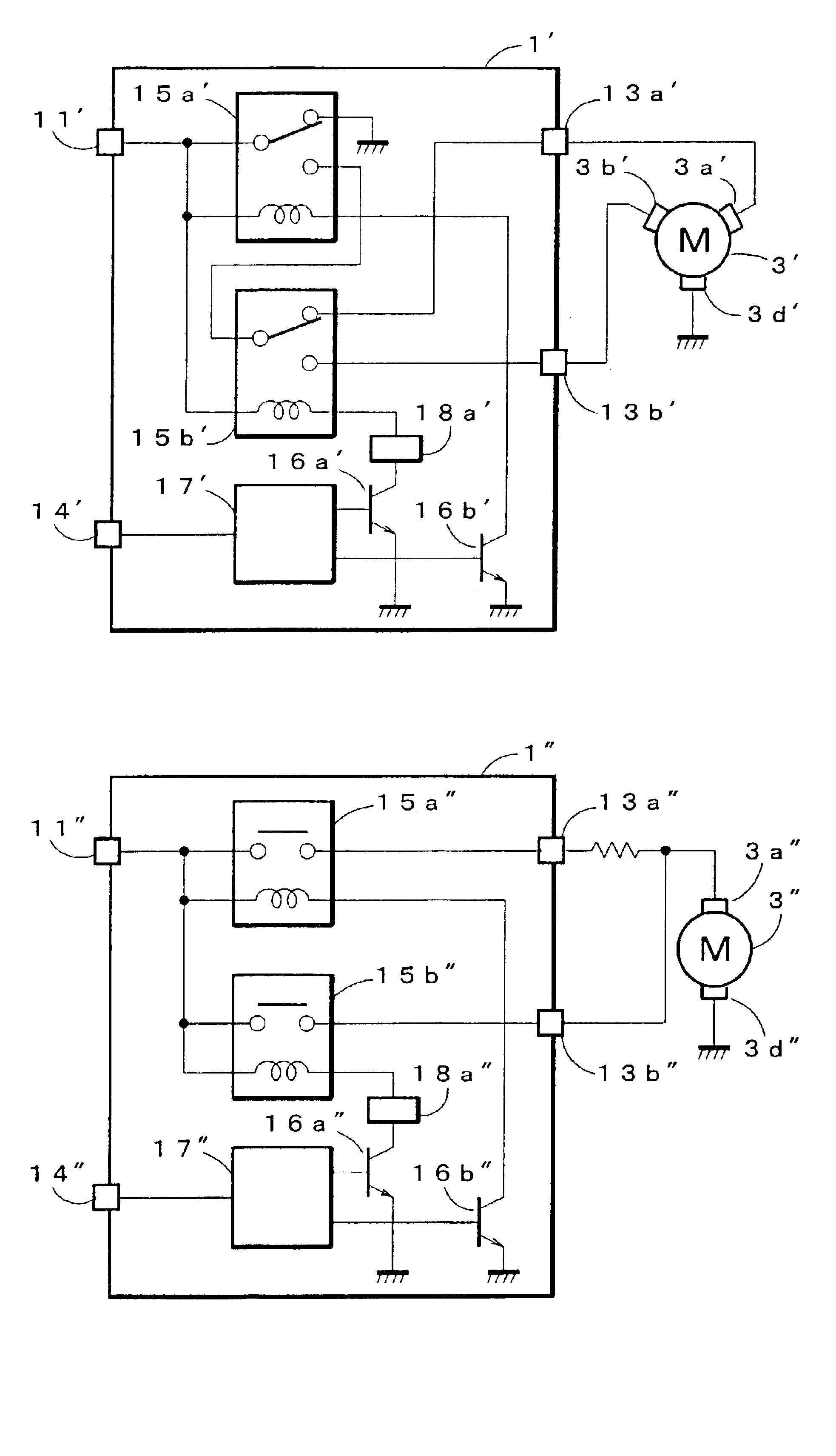
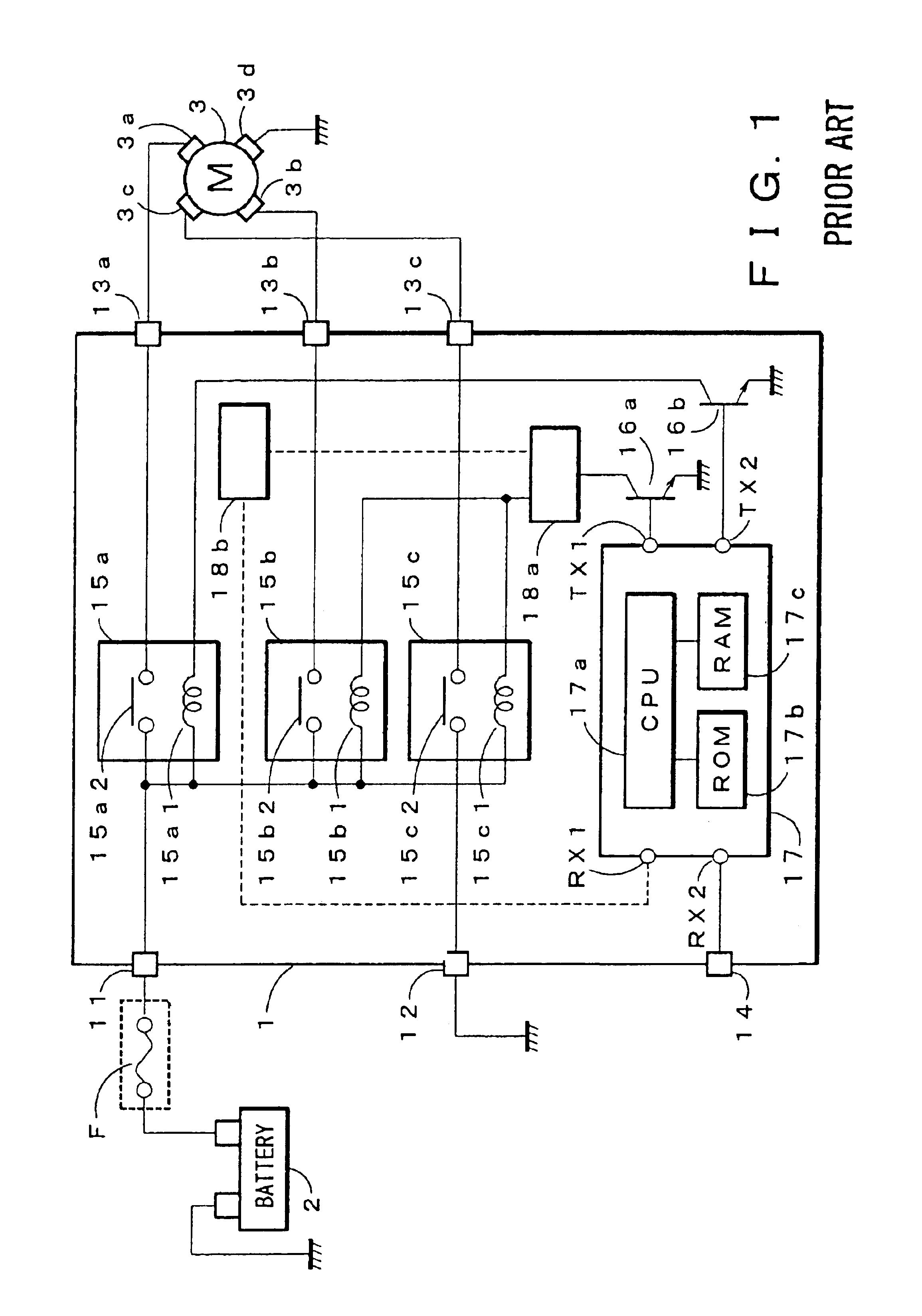
[0044]FIG. 1 is a circuit diagram of a motor control unit according to the present invention. As illustrated in FIG. 1, the motor control unit is applied to an electric junction box 1A for a radiator cooling fan. The electric junction box 1A includes function circuits. The electric junction box 1A is mounted on an automotive vehicle and is disposed between a 12V battery 2 and a motor 3 driving the radiator cooling fan. The electric junction box 1A accommodates various types of electronic and resin-made parts and is arranged with busbars that are conductors distributing an electrical power from the battery 2. The busbars will be discussed later with reference to FIGS. 6 and 7.

[0045]The electric junction box 1A has a power input terminal 11, a ground terminal 12, output terminals 13a and 13b, and a signal input terminal 14. The power input terminal 11 is connected to the battery 2, ...


PUM


Abstract

An electric motor control unit mounted in an automotive vehicle having a motor that is variable in its rotational speed. A temperature sensing element is arranged to contact a busbar so that relays permit switching operation in response to detection of abnormal heat generation. This controls an electrical power supply to the motor to decrease the rotational speed of the motor without complete stopping of the motor. The rotational speed of the motor returns to a normal speed from the decreased speed by switching operation of the relays with diminishing of the abnormal heat generation.

Description

BACKGROUND OF THE INVENTION[0001]1. Field of the Invention[0002]The present invention relates to an electric motor control unit for controlling a rotational speed of a motor used for a cooling fan of a radiator mounted on an automotive vehicle, particular to a motor control unit for controlling the rotational speed of the motor based on detection of overcurrent supplied to the motor.[0003]2. Description of the Related Art[0004]Conventionally, for overcurrent protection of a cooling fan of a radiator mounted on an automotive vehicle, fuses have been generally used. This causes various problems, which will be described hereinafter with reference to the accompanying drawings.[0005]FIG. 8 is a circuit diagram showing an example of a conventional motor control unit. The motor control unit is assembled in an electric junction box incorporated with a function circuit. The electric junction box is called as a junction block that is mounted on many recent automotive vehicles.[0006]An electri...

Claims


Application Information

Patent Timeline
Patent Type & Authority Patents(United States)
IPC IPC(8): H02P29/02F24F11/49F24F11/61F24F11/64F24F11/75F24F11/76B60H1/00F24F11/88F24F11/89H02P29/00
CPCH02P29/02Y10S388/934
Inventor ASHIYA, HIROYUKINAKAYAMA, MAKOTOSAITO, HIRONORI
Owner YAZAKI CORP
Learn More