Active or self-biasing micro-bolometer infrared detector

a micro-bolometer and detector technology, applied in the field of resistive micro-bolometer thermal infrared detectors, can solve the problems of limited functionality and detective performance, and noise of ‘fixed patterns’

Inactive Publication Date: 2005-08-09
IR SENSORS PTY LTD
View PDF10 Cites 18 Cited by
  • Summary
  • Abstract
  • Description
  • Claims
  • Application Information

AI Technical Summary

Problems solved by technology

In the case of a focal plane array of such detectors, small changes in material and dimensional parameters results in ‘fixed pattern’ noise, which must be corrected before the array can be usefully employed.
Th...

Method used


Image

  • Active or self-biasing micro-bolometer infrared detector
  • Active or self-biasing micro-bolometer infrared detector
  • Active or self-biasing micro-bolometer infrared detector

Examples


Embodiment Construction

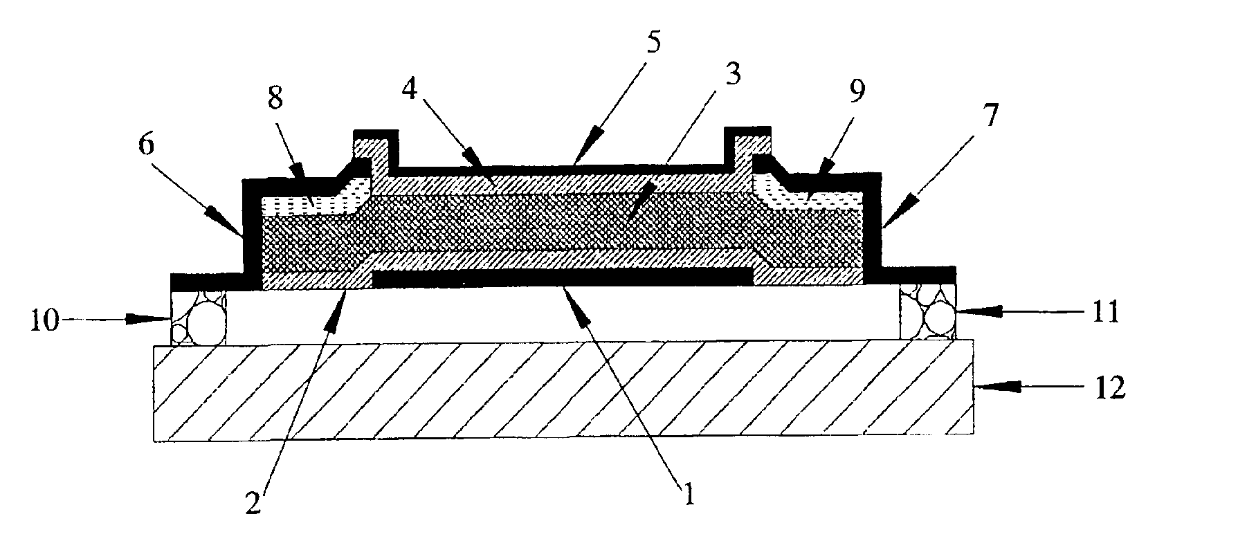
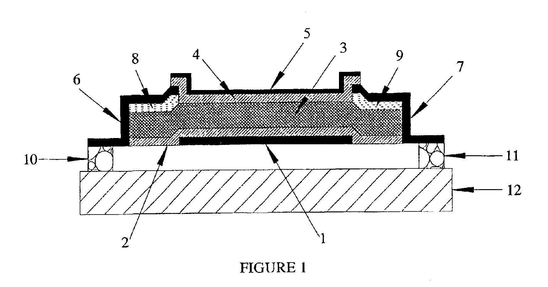
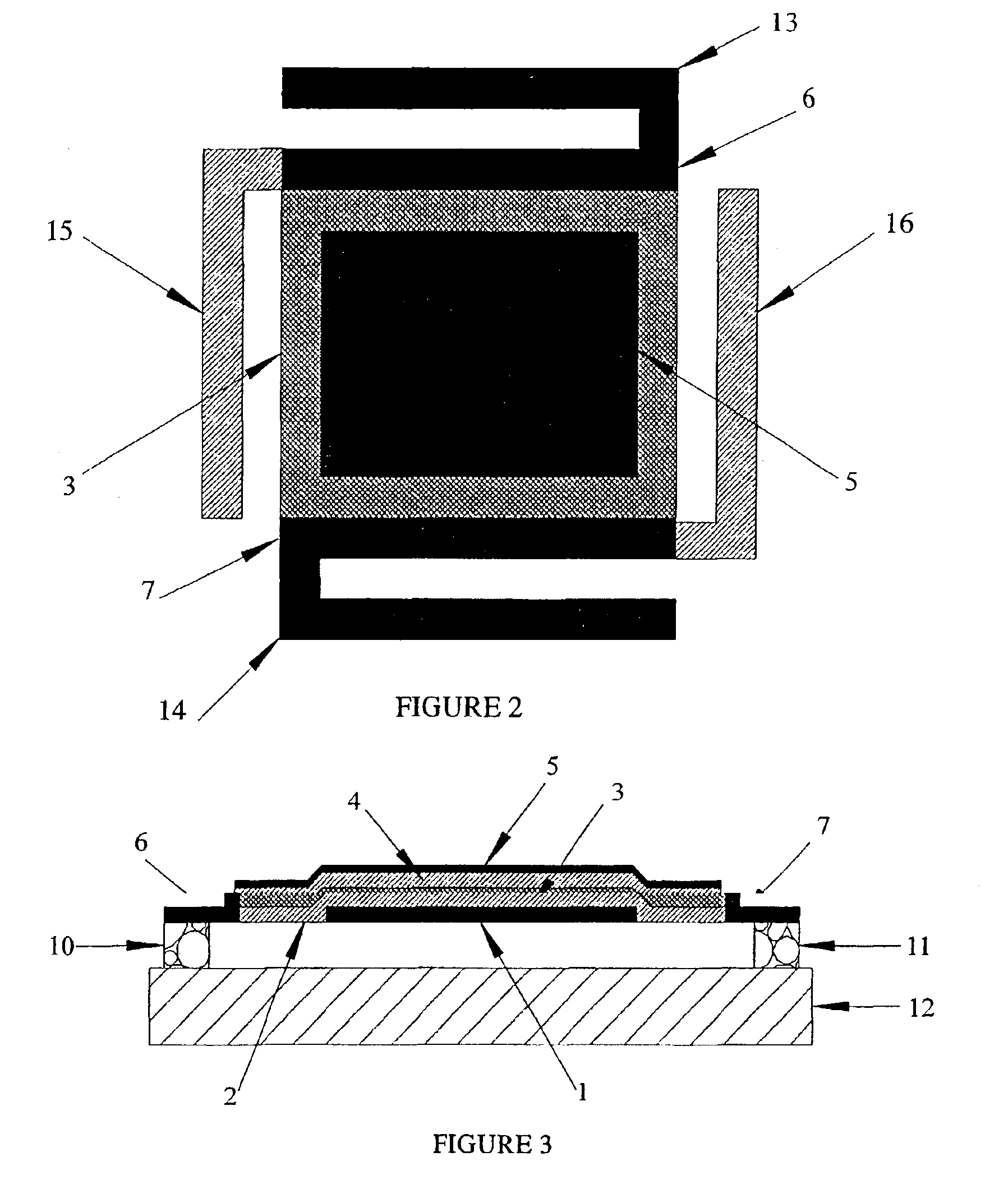
[0053]The following detailed description of the invention refers to the accompanying drawings. Although the description includes exemplary embodiments, other embodiments are possible, and changes may be made to the embodiments described without departing form the spirit and scope of the invention. Instead, the scope of the invention is defined by summary of the invention and appended claims, if any. Wherever possible, the same reference numbers will be used throughout the drawings and the following description to refer to the same and like parts.

[0054]FIG. 1 illustrates a bolometer including a thin film metal control electrode 1, which has the dual function of acting as an electrical contact and optical reflector, bottom insulator layer 2, semiconductor layer 3, top insulator 4, and top metal film 5. Electrical contact to the semiconductor layer 3 is made for the purpose of bias and signal readout by contacts 6 and 7. Heavily doped semiconductor layers 8 and 9 may advantageously be ...


PUM


Abstract

The detector includes a thin-film resistive component (3), at least two first electrical contacts (6, 7) electrically connected to the resistive component (3) that provide for biasing and signal readout, at least one second electrical contact (1) electrically connected to the resistive component (3) that provides bias control, an integral infra-red absorption means (4, 5) and thermal isolation means (10, 11). The detector may further include a readout integrated microcircuit (RIOC).

Description

BACKGROUND OF THE INVENTION[0001]The present invention relates to a resistance micro-bolometer thermal infrared detector. Unlike a conventional resistance bolometer that is an electronically passive device, the present invention is for a detector that can be operated in various electronically active modes, hence the term active bolometer.[0002]The concept of a thin film resistance bolometer has been known for many years, and a description can be found in various publications. See, for example, U.S. Pat. Nos. 4,574,263, 5,369,280, and 5,300,915, for a description of micro-bolometer operation and recent technologies.[0003]Conventional resistance bolometers are essentially passive devices, in that they function as a simple resistor component in an electronic circuit. In operation as an infrared detector the electrical resistance is caused to change by an incremental amount following radiation exposure as a consequence of the temperature coefficient of resistance of the detector materia...

Claims


Application Information

Patent Timeline
IPC IPC(8): G01J5/20H01L31/0216H01L31/08H01L31/09
CPCG01J5/20H01L31/02165H01L31/09
Inventor LIDDIARD, KEVIN
Owner IR SENSORS PTY LTD
Why Eureka
Try Eureka