
Resuscitation device

a technology of resuscitation device and chest compression, which is applied in the direction of artificial respiration, heart stimulation, therapy, etc., can solve the problems of inability to maintain adequate chest compression for more than a few minutes, brain damage of people suffering cardiac arrest, and difficulty if not impossible to maintain adequate chest compression. , to achieve the effect of convenient us

Inactive Publication Date: 2005-08-09
ZOLL CIRCULATION
View PDF51 Cites 18 Cited by
  • Summary
  • Abstract
  • Description
  • Claims
  • Application Information

AI Technical Summary

Benefits of technology

The patent describes a portable device that can be used for chest compression in cardiac arrest patients. The device is compact, portable, and easy to use by by-standers with little training. It is powered by a small battery and can be used for both CPR and defibrillation. The device includes an interlock system that uses a heart monitor or EKG to diagnose the patient and initiate or prohibit belt operation. The device can also communicate with medical personnel through a telemetry system and can be programmed with location information or provided with GPS capabilities. The technical effects of the patent are that it provides a portable and effective tool for administering CPR and other therapy to cardiac arrest patients, even in situations where expert supervision is not available.

Problems solved by technology

During cardiac arrest, the heart stops pumping blood, and a person suffering cardiac arrest will soon suffer brain damage from lack of blood supply to the brain.
However, when chest compression is required for long periods of time, it is difficult if not impossible to maintain adequate compression of the heart and rib cage.
Even experienced paramedics cannot maintain adequate chest compression for more than a few minutes.
Thus, long periods of CPR, when required, are not often successful at sustaining or reviving the victim.
The victim must first be installed into the device, and the height and stroke length of the piston must be adjusted for the patient before use, leading to delay in chest compression.
These devices are not clinically more successful than manual chest compression.
The force needed to provide effective chest compression creates risk of other injuries.
Thus the risk of injury attendant to chest compression is high, and clearly may reduce the chances of survival of the victim vis-à-vis a resuscitation technique that could avoid those injuries.
Chest compression will be completely ineffective for very large or obese cardiac arrest victims because the chest cannot be compressed enough to cause blood flow.
Chest compression via pneumatic devices is hampered in its application to females due to the lack of provision for protecting the breasts from injury and applying compressive force to deformation of the thoracic cavity rather than the breasts.
Hypoxia sets in about two minutes after cardiac arrest, and brain damage is likely after about four minutes without blood flow to the brain, and the severity of neurologic defect increases rapidly with time.
A delay of two or three minutes significantly lowers the chance of survival and increases the probability and severity of brain damage.
However, CPR and ACLS are unlikely to be provided within this time frame.
They are generally capable of providing CPR but cannot provide drugs or intravascular access, defibrillation or intubation.
Though defibrillation and drug therapy is often successful in reviving and sustaining the victim, CPR is often ineffective even when performed by well-trained first responders and ACLS personnel because chest compression becomes ineffective when the providers become fatigued.
By-standers may be unable to confidently determine if chest compression is needed, or when it should be stopped.
However, some situations in which the device might be used may call for expert supervision of the CPR process by emergency medical technicians, emergency room doctors, or cardiologists.

Method used


Image

  • Resuscitation device
  • Resuscitation device
  • Resuscitation device

Examples


Embodiment Construction

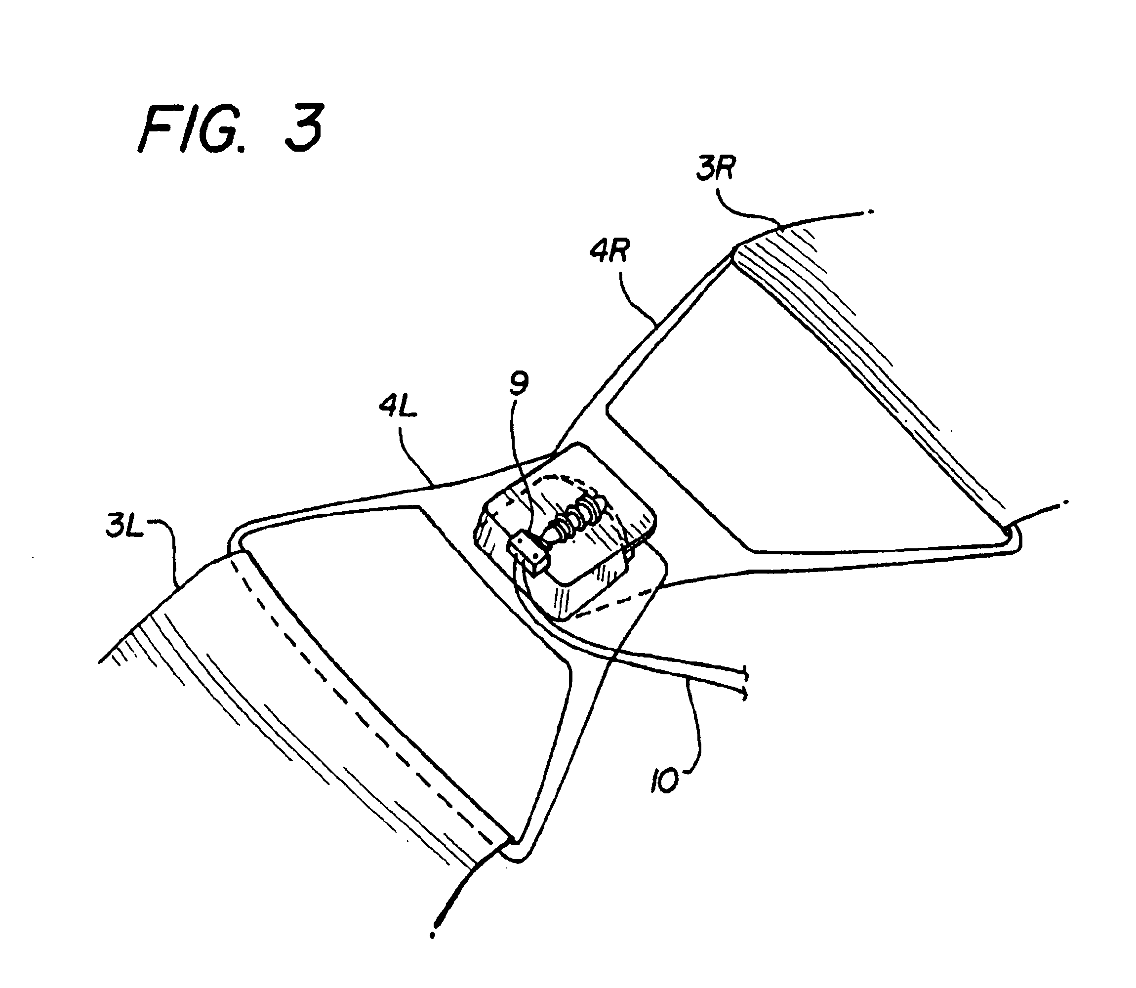
[0027]FIG. 1 shows a simplified version of the resuscitation device 1. The mechanisms used for compressing the chest includes compression assembly 2 which includes a chest compression belt 3 with buckles 4L and 4R, a friction liner 5, a support board 6 and a motor driven spool assembly 7. The support board 6 is placed under a cardiac arrest victim, and the compression belt 3 and friction liner 5 are wrapped around the victim's chest. The chest compression belt, having a left side 3L and a right side 3R, is buckled over the victims chest by latching the buckles 4L and 4R together. In this configuration, the friction liner 5 will fit between the chest compression belt 3 and the victim and any clothes worn by the victim. The compression belt may be made of any strong material, and sailcloth has proven adequate for use. The compression belt may also be referred to as a vest, corset, girdle, strap or band. The friction liner may be made of Teflon®, Tyvek™ or any other low friction materi...


PUM


Abstract

A resuscitation device for automatic compression of victim's chest using a compression belt which exerts force evenly over the entire thoracic cavity. The belt is constricted and relaxed through a motorized spool assembly which repeatedly tightens the belt and relaxes the belt to provide repeated and rapid chest compression. An assembly includes various resuscitation devices including chest compression devices, defibrillation devices, and airway management devices, along with communications devices and senses with initiate communications with emergency medical personnel automatically upon use of the device.

Description

[0001]This application is a continuation of U.S. application Ser. No. 09 / 615,979 filed Jul. 14, 2000, now U.S. Pat. No. 6,599,258, which is a continuation of U.S. application Ser. No. 08 / 924,555 filed Aug. 27, 1997, now U.S. Pat. No. 6,090,056.FIELD OF THE INVENTIONS[0002]This invention relates to emergency medical devices and methods.BACKGROUND OF THE INVENTIONS[0003]Cardiopulmonary resuscitation (CPR) is a well-known and valuable method of first aid. CPR is used to resuscitate people who have suffered from cardiac arrest after heart attack, electric shock, chest injury and many other causes. During cardiac arrest, the heart stops pumping blood, and a person suffering cardiac arrest will soon suffer brain damage from lack of blood supply to the brain. Thus, CPR requires repetitive chest compression to squeeze the heart and the thoracic cavity to pump blood through the body. Very often, the victim is not breathing, and mouth to mouth artificial respiration or a bag valve mask is use...

Claims


Application Information

Patent Timeline
Patent Type & Authority Patents(United States)
IPC IPC(8): A61H31/00A61H11/00
CPCA61H11/00A61N1/3987A61H31/006A61H31/008A61N1/0472A61N1/39A61N1/3968A61N1/3993A61H31/004A61H31/005A61H2031/003A61H2201/0173A61H2201/018A61H2201/5007A61H2201/501A61H2201/5012A61H2201/5043A61H2201/5048A61H2201/5058A61H2201/5089A61H2201/5097A61H2230/04A61H2230/207A61M16/06A61M16/10A61M2202/0208A61M2209/08A61N1/046A61N1/0492A61M2205/0222A61N1/39044
Inventor BYSTROM, STEVEN R.SHERMAN, DARREN R.MOLLENAUER, KENNETH H.
Owner ZOLL CIRCULATION
Learn More