Hold down assembly, with tubular container transport apparatus and methodology incorporating the same

a technology of tubular container and assembly, which is applied in the direction of mechanical conveyors, conveyor parts, packaging, etc., can solve the problems of improper ejection of filled tubes, improper dislodgement of tube holders, and improper dislodgement of rods, so as to reduce the risk of tube holders being dislodged, prevent dislodgement, and easy construction

Inactive Publication Date: 2005-08-09
REAGENT CHEM & RES
View PDF8 Cites 0 Cited by
  • Summary
  • Abstract
  • Description
  • Claims
  • Application Information

AI Technical Summary

Benefits of technology

[0012]Still a further object of the present invention is to provide such a hold down assembly which reduces the risk of dislodgement of tube holders during the production process.
[0013]It is still a further object of the present invention to provide such a hold down assembly which is relatively easily constructed and which may be retrofitted for use with existing unload stage constructions.
[0014]It is still yet another object of the present invention to provide a method for preventing dislodgement, or reducing the risk of dislodgement, of tube holders during the unload / ejection stage of the manufacturing process for creating filled tube products.
[0019]It is preferred that the lower piece be removably and magnetically seated on the mounting plate through which the ejector rod travels so that, in the event of a collision between the hold down assembly and a traveling tube holder, the hold down assembly can break away from its magnetic coupling to the mounting plate. To this end also, the hold down assembly is constructed to prevent damage to the ejector rod in the event of a collision. This is accomplished by a slotted channel formed in each of the upper and lower pieces. More particularly, the lower piece preferably includes a slotted channel extending between its opposed ends which is sized and adapted to register with an elevated alignment notch on the mounting plate so that this slotted channel is oriented in an upstream facing direction when magnetically coupled to the mounting plate. The upper piece preferably also includes a slotted channel which extends less than its height so that it resembles an archway. The upper piece slotted channel is rotatably alignable with the slotted channel associated with the lower piece when the hold down assembly is telescopically mounted. In this manner, an inadvertent collision between the traveling tube holder and the hold down assembly will enable the hold down assembly to break away from the mounting plate, whereby the ejector rod can passes through the aligned slotted channels and avoid contact with the hold down assembly.

Problems solved by technology

Unfortunately, it is not uncommon during the unload stage for the unload assembly and the associated tube holder to improperly align in registration with one another such that the ejector rod does not properly contact the tube as it plunges upwardly in an effort to knock out the tube from its holder.
This can cause improper ejection of the filled tube, dislodgement of its tube holder, or other problems which disrupt the manufacturing process.

Method used


Image

  • Hold down assembly, with tubular container transport apparatus and methodology incorporating the same
  • Hold down assembly, with tubular container transport apparatus and methodology incorporating the same
  • Hold down assembly, with tubular container transport apparatus and methodology incorporating the same

Examples


Embodiment Construction

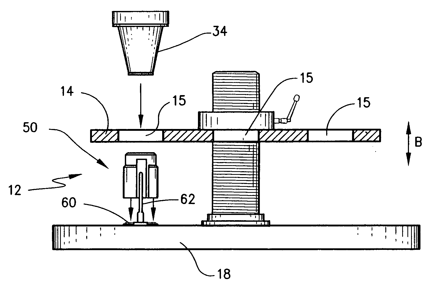
[0037]The present invention relates in one sense, to a tube hold down assembly that may be used to improve the efficiency of the manufacturing process involved in the production of filled tube products. Accordingly, the present invention not only contemplates the mechanical structure of such a hold down assembly, but also the method that is inherent in the structure, all of which is described below. Moreover, it should be understood that, while the present invention is described with respect to cylindrical tubular containers having flexible sidewalls, the ordinarily skilled artisan would be able to employ both the process and the apparatus with containers of different shapes and configurations with an appreciation of the teachings herein.

[0038]To better appreciate the environment of the present invention, reference is made initially to FIG. 1 which depicts a tubular container transport apparatus 10 for use during the manufacturing process involved in producing filled tube products. ...


PUM


Abstract

A hold down assembly for use in a tubular container transport apparatus comprises upper and lower pieces movably mounted relative to one another. Preferably the lower piece is removably seated on a mounting plate of the transport apparatus and the upper piece is adapted to magnetically interact with a tube holder carrying a filled tube product, such that the tube holder may be retained in registered alignment relative to an ejector rod during ejection of the filled tube product. A tubular container transport apparatus and a methodology for ejecting a filled tube product with a reduced risk of dislodgement are also provided.

Description

[0001]This application claims benefit of Provisional Application No. 60 / 423,306, filed Nov. 1, 2002.FIELD OF THE INVENTION[0002]The present invention broadly relates to apparatus for use during the manufacturing process of producing filled-tube products. More particularly, the present invention is directed to hold down assemblies for use during the ejection stage of the manufacturing process. The invention specifically concerns hold down assemblies which reduce or prevent the risk of dislodgement of tube holders during the ejection stage of the manufacturing process, as well as methodologies incorporating the same.BACKGROUND OF THE INVENTION[0003]The packaging of products for storage and consumption is a significant global industry. Various known packages include cartons, boxes, cans, tubes, and pouches, to name a few. Packaged products encompass virtually any type of product that is available for consumption from large appliances to small incidental items.[0004]One of the major typ...

Claims


Application Information

Patent Timeline
IPC IPC(8): B65G47/04B65B43/50
CPCB65B43/50
Inventor SONNTAG, DONALD W.JOHNSON, JACK L.JONES, RANDY
Owner REAGENT CHEM & RES
Why Eureka
Try Eureka